Walk into any civil engineering office ten years ago, and you’d find the same thing: rolls of 2D drawings, CAD files organized in folders nobody could fully navigate, and spreadsheets holding quantity data that was already outdated the moment a design change came through.
That was just the job. Everyone accepted it.
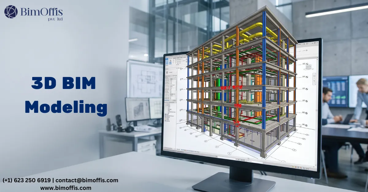
But something has shifted over the last few years, and it’s not subtle anymore. Civil engineers working on bridges, highways, tunnels, and drainage networks are starting to work the same way building teams have worked for years, inside intelligent 3D models that carry real data, update automatically, and talk to other software.
It hasn’t been a smooth or fast transition. But it’s happening, and the engineers leading it are not going back.
Why Civil Engineering Took Longer to Adopt BIM
Buildings got BIM first for a simple reason, the software was built around buildings. Revit was designed for floors, walls, roofs, and rooms. Civil work didn’t fit that mould, and for a long time, the tools available for infrastructure were either clunky or expensive, or both.
Civil 3D existed, but calling early Civil 3D a BIM tool would be generous. It was intelligent CAD, better than plain AutoCAD, but not the kind of model-based environment that architects were working in.
What changed things was a combination of better software, stronger client demand, particularly from government infrastructure clients pushing for BIM deliverables, and a growing number of engineers who had seen what proper 3D coordination could do on complex projects and didn’t want to go back to drawing boards.
What Civil Engineers Are Actually Doing With It Now
Road and Highway Corridor Modeling
This is where a lot of civil teams first see the real value. A corridor model in Civil 3D or similar software isn’t just a 3D picture of a road. It’s a parametric model where the geometry responds to changes in alignment, grade, and cross-section design.
Move the centerline 15 meters to the left. The entire corridor, cut slopes, fill slopes, drainage swales, pavement layers, adjusts with it. Earthwork volumes recalculate. Cross-sections update.
On a traditional 2D project, that kind of change means days of redrawing. In a corridor model, it’s a few hours at most, and the quantities are already updated before the engineer finishes their coffee.
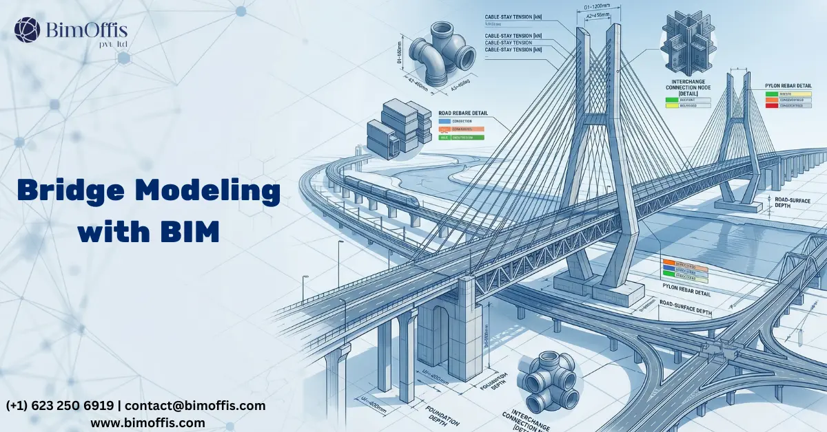
Bridge Design and Structural Coordination
BIM for infrastructure bridges has come further than most people outside the industry realize. Parametric bridge models now allow engineers to build complete superstructures, decks, girders, piers, abutments, bearings, expansion joints, with geometry driven by span lengths, load parameters, and material specifications.
What makes this genuinely useful rather than just impressive is the connection to structural analysis. Engineers can push geometry from the BIM model into finite element analysis software, run load cases, and bring results back into the model environment. The design and the analysis stay connected rather than existing as separate files that someone has to manually keep in sync.
On a multi-span viaduct project, this means the same model that was used to explore span options during concept design can carry forward, with full continuity of data, into detailed engineering. Nothing gets redrawn from scratch. Nothing gets lost in translation between teams.
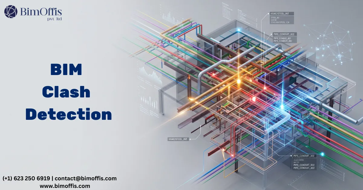
Underground Coordination and Clash Detection
Anyone who has worked on a tunnel, underpass, or buried utility corridor knows the coordination headaches involved. Structural lining geometry, drainage inverts, ventilation ducts, existing buried services, utility crossings, everything has to coexist in a space you can’t see until you’ve already dug it.
Clash detection on a federated infrastructure model catches these conflicts on screen. A drainage pipe running through a pile cap. A utility crossing conflicting with a culvert invert. A retaining wall foundation overlapping with an existing sewer.
Finding those clashes during design costs almost nothing. Finding them during construction costs a lot, in time, money, and the kind of difficult conversations nobody wants to have on site.
Quantities That Actually Update
Quantity surveying on infrastructure projects has always been labour-intensive. Earthwork volumes, pavement areas, drainage lengths, structure counts, all of it measured manually from 2D drawings, all of it vulnerable to human error, and all of it needing to be redone every time the design changed.
A properly built BIM model generates most of these quantities directly. Earthwork cut and fill volumes come from the corridor model compared against existing ground. Structural quantities schedule out from the model components. When the design changes, the numbers change with it.
The estimator still needs to apply rates, assess risk, and think about buildability. But the tedious measurement work, which added no intellectual value and created significant error risk, largely disappears.
The Asset Handover Argument
Here’s the conversation that’s starting to happen more often between infrastructure clients and their engineering teams, what happens after this project is built?
A bridge doesn’t get demolished after construction. It gets maintained, inspected, load-rated, and eventually rehabilitated over a lifespan measured in decades. All of that work needs information, element records, material data, inspection histories, maintenance schedules.
When a bridge is modeled properly with structured asset data embedded from the start, that information transfers directly to the asset management system at handover. The maintenance team inherits a working record of the structure rather than a pile of PDFs and a fading institutional memory.
That’s a different conversation than “BIM saves time on drawings.” It’s a conversation about the value of information over the entire life of an asset.
It’s Not All Figured Out Yet
Infrastructure BIM still has real problems. Data standards vary between clients and across borders. Not every contractor has the capability to work with model-based deliverables. Survey data quality on legacy infrastructure projects is often poor enough to undermine the model built on top of it.
And the honest truth is that many civil engineers are still early in the learning curve. The tools demand more than traditional CAD, and experience takes time to build.
Where Things Are Heading
The civil engineers who have invested in BIM for infrastructure bridges and wider infrastructure work aren’t doing it because a client asked them to tick a box. They’re doing it because once you’ve coordinated a complex bridge project in 3D, caught twenty clashes before they reached site, and handed over a structured asset model at completion, working any other way feels like a step backward.
That feeling spreads. Slowly at first, then quickly. Ready to find out what your project will cost? Find out here.
Frequently Asked Questions from Clients
What is BIM for infrastructure?
It’s the use of intelligent 3D modeling on civil projects, roads, bridges, tunnels, drainage, where the model carries real data, not just geometry.
Can BIM be used for bridge design?
Yes. Engineers model full bridge structures, decks, piers, abutments, and bearings with parameters connected directly to structural analysis software.
Is Revit used for civil infrastructure projects?
Revit is mainly building-focused. Civil engineers typically use Civil 3D, Bentley OpenBridge, or Infraworks for infrastructure BIM work.
How does BIM help with earthwork quantities?
The corridor model calculates cut and fill volumes automatically against existing terrain. When design changes, quantities update instantly, no manual remeasuring.
What is clash detection in infrastructure projects?
It’s the process of checking whether elements from different disciplines, structure, drainage, and utilities, conflict with each other inside the federated model before construction starts.
Is BIM mandatory for infrastructure projects?
In many countries, government infrastructure clients now require BIM deliverables. It varies by region and project size.