Architectural drawings are the primary tool architects use to communicate design intent. Clients, engineers, contractors, regulatory authorities, and construction teams all depend on these drawings. They need to understand what is being built, how it is organised, what it should look like, and what standards it must meet.
The term covers a broad range of document types. Each type serves a different purpose at a different stage of the project. For students, clients, and contractors alike, it helps to know what each type does and when it appears in the timeline.
This guide walks through the full range of architectural drawings. It explains what each one actually does.
What Architectural Drawings Are and What They Do
The Purpose of Architectural Drawings
Architectural drawings serve two fundamental purposes. First, they communicate design intent. Second, they provide the instructions from which builders construct buildings.
These two purposes are related but distinct. For example, a conceptual sketch communicates design intent to a client early on, while the design is still forming. A detailed construction document, by contrast, gives a contractor precise instructions for building the structure. Both count as architectural drawings. However, they serve different audiences with different levels of detail at different stages.
In addition, architectural drawings function as legal documents, not just technical ones. Construction documents form part of the building contract. They define the scope of work the contractor must deliver. When drawings and specifications stay clear, complete, and well-coordinated, the contract itself is well-defined. Ambiguity, on the other hand, is usually where disputes arise.
How Architectural Drawings Relate to BIM
Architects traditionally produced drawings by hand. Later, they used CAD software. Now, many generate drawings directly from BIM models. When drawings come from a BIM model, the floor plan, section, elevation, and schedule all derive from one source. So, changing the design in the model updates every view automatically.
This matters for reliability. BIM-produced drawings stay coordinated with each other because they share a single source. Manually maintained drawing sets, however, only stay as coordinated as the people updating them. On a large, evolving project, that discipline is rarely perfect.
Types of Architectural Drawings
Site Plans
A site plan shows the building in the context of its site. It includes the building’s footprint, its position relative to boundaries and neighbouring structures, and its orientation to north. It also shows access routes, parking, landscaping, and other site elements within scope.
Site plans serve multiple audiences at once. They give the client and design team a picture of how the building sits on its site. Meanwhile, they give the planning authority what it needs to assess the development’s impact on the surroundings. For the contractor, they provide the information needed to set out the building correctly.
Site plans are typically required for planning permission submissions. As a result, they’re often the first drawing type people outside the design team ever see.
Floor Plans
Floor plans are the most fundamental architectural drawing type. Usually, they’re the first drawings people encounter when looking at a design. A floor plan shows a horizontal cut through the building at a specific level. Typically, it shows room layouts, wall positions, door and window locations, and key dimensions.
Floor plans work at various scales, depending on their purpose. A small-scale overall plan gives an overview of the building’s organisation, fitting the whole floor onto one sheet. Large-scale plans, on the other hand, zoom into specific areas or room types. At that scale, dimensions and annotations stay easy to read.
Good floor plans show much more than walls and openings. For instance, they show floor finishes, furniture layouts where relevant, and structural elements. They also point to where sections and elevations give additional information. As a result, a well-prepared floor plan rewards careful reading.
Reflected Ceiling Plans
A reflected ceiling plan shows the ceiling as if viewed from below. Architects draw it as a plan, not a perspective. This convention keeps it consistent in orientation with the floor plan below it. That, in turn, makes cross-referencing between the two straightforward.
These plans show ceiling heights, materials, and the positions of ceiling-mounted elements. Light fittings, HVAC diffusers and grilles, sprinkler heads, and smoke detectors all appear here. So do architectural ceiling features, such as coffers, bulkheads, or exposed structure.
For contractors, reflected ceiling plans matter for coordination. They align architectural finishes with the MEP services sharing the ceiling zone. Indeed, a well-coordinated plan removes a major source of site conflict.
Elevations
Elevations show a building’s external and internal faces from a straight-on viewpoint. Picture standing directly in front of a surface and looking at it. External elevations cover every face of the exterior. Internal elevations, meanwhile, show specific room walls where plans and sections can’t communicate the design fully.
External elevations communicate a building’s architectural character. They show the facade composition, the size and position of windows and doors, and the materials and their boundaries. They also show any features that define the exterior appearance. For planning submissions especially, elevations draw the most scrutiny, since they show the building’s visual impact.
Internal elevations matter most for spaces with specific requirements. A kitchen elevation, for example, shows cabinet layout, appliance positions, and the splashback arrangement. A bathroom elevation similarly shows sanitaryware layout, tile extent, and fitting positions. Contractors and fit-out teams rely on these to install correctly.
Sections
Sections cut through a building vertically. They reveal floor-to-floor heights, the relationship between structure and the spaces it bounds, ceiling heights, and how spaces at different levels relate visually.
In fact, sections best communicate a building’s three-dimensional spatial quality. Consider a double-height atrium connecting two floors, or a mezzanine creating an intimate zone within a larger space. Consider, too, a high-ceilinged entrance hall against the lower-ceilinged rooms beyond it. Sections capture these qualities in ways floor plans simply cannot.
Furthermore, sections through the building envelope reveal how the construction actually works. They show how the roof meets the wall, how the floor meets the ground, and how the building manages weather, thermal performance, and structural loads at these junctions.
Detail Drawings
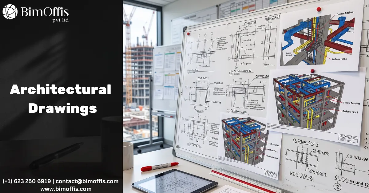
Detail drawings show specific conditions at a large scale. They provide the precision construction needs for junctions, transitions, and special conditions the overall drawings can’t capture clearly.
A typical detail might show the junction between two wall types. It might show how a window frame connects at its head, jamb, and sill. It might show how a floor finish meets a wall finish at a skirting, or how a roof edge manages waterproofing, insulation, and structural connections together.
In short, details are where construction quality lives or dies. Well-designed, clearly drawn details let contractors build correctly. When critical conditions go underdetailed, though, contractors must decide on their own. Those decisions aren’t always the right ones.
Schedules
Schedules pull specific information from the drawings into tables. These tables support procurement, installation, and inspection. Technically, schedules count as drawings since they form part of the architectural package, even though they present tabular rather than graphic information.
Door schedules, for instance, list every door with its size, type, fire rating, acoustic performance, hardware, and finish. Window schedules do the same for glazed elements. Room finish schedules specify the floor, wall, and ceiling finishes for every space. Equipment schedules list every mechanical and electrical item with its specification, location, and connection requirements.
When schedules come from a BIM model rather than a manual process, they reflect the current design automatically. Add a door to the model, and it appears in the door schedule. Change a room finish, and the schedule updates too. This consistency removes a major source of procurement error and site confusion.
What Makes Architectural Drawings Good
Good architectural drawings communicate clearly to their audience. They stay accurate, consistent with one another, and complete enough to answer the questions readers actually have.
For construction documents specifically, good drawings cover every condition the building will encounter. They don’t leave unusual or difficult conditions undocumented. They stay internally consistent, so the floor plans, sections, elevations, and schedules all tell the same story. They also coordinate with the structural and MEP drawings, keeping the full contract set free of conflicts that cause disputes and rework.
The Bottom Line
Architectural drawings remain the primary communication tool of the design process. They carry design intent from the earliest sketches through to the construction documents contractors build from. Anyone involved in a building project benefits from understanding this range of drawing types, from the client approving a design to the contractor building from it.
Ultimately, drawing quality shapes construction quality. Clear, complete, well-coordinated drawings produce smooth construction. Incomplete or ambiguous ones, on the other hand, create the coordination failures, RFIs, and disputes that make projects harder and costlier than they need to be.
Turn your architectural concepts into build-ready documentation by consulting our architectural drafting experts for accurate drawings and BIM solutions.
Frequently Asked Questions from Clients
What are architectural drawings?
They are technical drawings that show a building’s layout, dimensions, and construction details.
Why are architectural drawings important?
They help architects, engineers, and contractors plan and construct buildings accurately.
What types of architectural drawings are commonly used?
Floor plans, elevations, sections, site plans, and detail drawings.
Who prepares architectural drawings?
Architects, architectural designers, and drafting professionals.
How do BIM and architectural drawings work together?
BIM enhances traditional drawings with intelligent 3D models and project data.
What software is used to create architectural drawings?
AutoCAD, Revit, Archicad, and other CAD/BIM software.