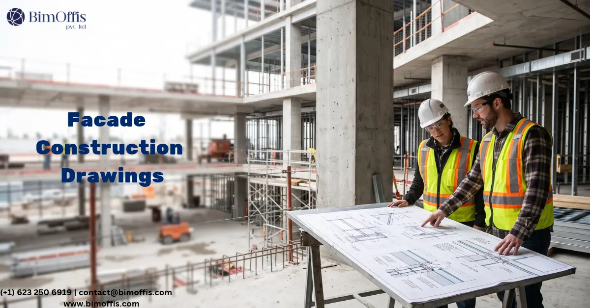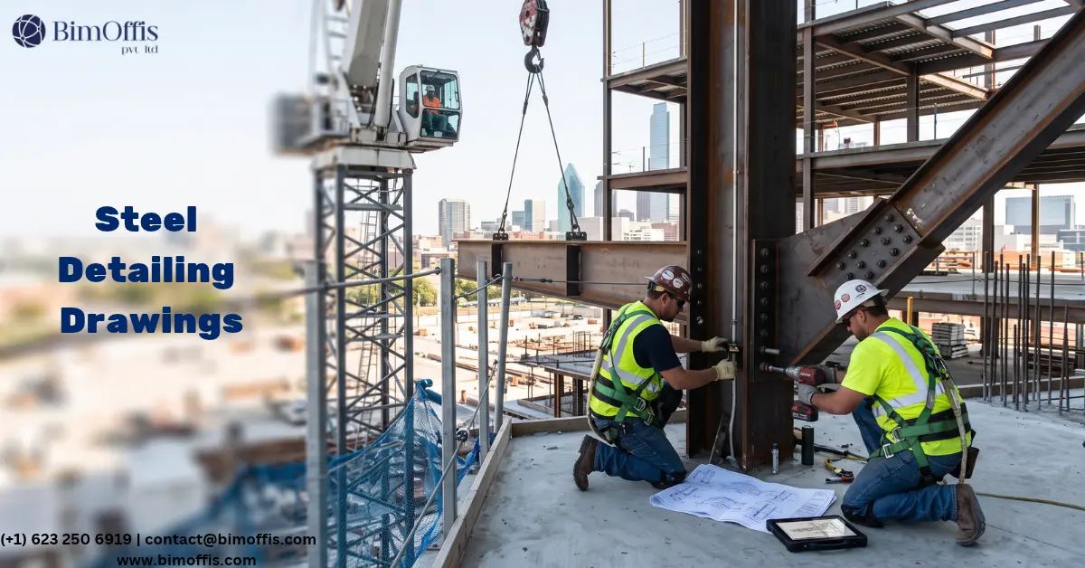
Structural steel detailing takes a structural engineer’s steel design and turns it into fabrication drawings, connection details, and erection documentation. A steel fabricator needs these documents to manufacture the steel. Similarly, a steel erector needs them to assemble it on site.
Structural engineers, steel fabricators, and site managers all recognise a common gap. Design drawings show the structural intent. For instance, they show member sizes, loading conditions, connection types, and the overall structural system. But they don’t show the exact geometry of every connection. Specifically, they skip the specific weld sizes, the precise hole patterns, and the exact cut lengths that account for fabrication tolerances and erection clearances. Complex built-up sections need a fabrication sequence too, and design drawings rarely provide one.
Structural steel detailing fills that gap. Essentially, good detailing means the steel coming off the shop floor fits the structure correctly. It connects as the engineer designed. And it erects on programme, without the expensive surprises poor detailing consistently produces. Poor detailing, on the other hand, causes problems during erection: a beam end that doesn’t match its connection bracket, a column base plate with bolt holes in the wrong pattern, or a connection that needs modification before crews can make the steel safe.
Ultimately, every one of these problems costs more to fix on site than accurate detail drawings would have cost upfront.
What Structural Steel Detailing Covers
Structural steel detailing produces several categories of documentation. Together, they cover every aspect of a steel structure, from individual component fabrication through to complete building erection.
General Arrangement Drawings
General arrangement drawings show the complete structural steel layout. Every member carries a unique piece mark and sits at its correct location, oriented correctly relative to the members it connects to. As a result, fabrication shops and erection teams both rely on these drawings for a complete overview of the steel package and the reference points they need to locate each member.
Individual Member Drawings
Individual member drawings cover every distinct steel section in the project. Each drawing shows the exact length of the section, accounting for connection clearances and fabrication tolerances. It also shows the cross-sectional profile, material grade, and end preparation required at each end. Additionally, hole positions and sizes appear here, along with the positions of connection plates and cleats, plus the weld sizes and types at every attachment.
Connection Details
Connection details show the specific configuration of every structural connection in the frame: the bolted beam-to-column connection, the welded moment connection, the column base plate to foundation connection, and the brace connection at a gusset plate. Each detail includes the required components, exact dimensions, weld or bolt specifications, and the edge distances and spacings that meet relevant code requirements. Where needed, special conditions get their own notes too.
Erection Drawings and Schedules
Erection drawings show the sequence and method for installing the steel. For example, they indicate which members go in first to create a stable structure. They also specify the temporary bracing needed before the permanent system is complete, plus the crane capacities and lift configurations the heaviest members require. Consequently, good erection drawings protect structural stability during the build and the safety of crews working at height.
Furthermore, bolt and weld schedules list every bolt group and weld in the structure. These schedules give procurement and inspection teams the specifications and quantities they need.
Why Structural Steel Detailing Quality Matters
The Cost of Getting It Wrong
Structural steel fabrication is expensive, and it doesn’t reverse easily. Once a shop cuts a section to length, drills a specific hole pattern, and welds on its connection components, fixing a mistake gets costly. Sometimes, replacement is the only option.
For example, take a beam with its connection end plates welded in the wrong orientation. In this case, crews either cut off the end plates and reweld them correctly, or replace the beam entirely. Similarly, a column base plate with anchor bolt holes in the wrong pattern creates a related problem: nobody can install it until someone modifies the foundation bolt pattern or the plate itself. Either way, both situations cost more in time and money than correct detailing would have cost.
Moreover, the programme consequences compound quickly. Structural steel typically sits on the critical path of any steel-framed project, so every other trade depends on the steel going up on schedule. Therefore, when erection stops because of a fabrication error, the delay ripples through every trade that follows. In the end, a detailing error costs the price of the fix plus the price of the delay it causes.
The Coordination Function of the Review Process
Structural steel detailing includes a review step. Here, the structural engineer checks the submitted shop drawings against the design drawings before fabrication starts. This review catches gaps between how the detailer interpreted the design and what the engineer actually intended.
For instance, catch a connection configuration issue at this stage, and the fix is simple: a revised drawing and a comment response. However, let the same issue slip through to the fabrication shop, and the fix means reworked or replaced steel. That’s why the review process ranks among the most financially significant steps in the detailing workflow. Ultimately, its quality shapes much of the value the whole process delivers.
How Good Structural Steel Detailing Works in Practice
Starting From Accurate Design Information
Good detailing starts with complete, current, and accurate design information. Structural drawings need to show member sizes, connection types, material grades, loading conditions, and any special requirements. Additionally, detailers need access to the engineer’s connection design calculations, so they can verify each connection has the capacity those calculations require.
However, working from incomplete or outdated information creates a problem: shop drawings that reflect an earlier version of the design, not the current one. Once the structural design changes, someone needs to revise the shop drawings. If the team skips that step before fabrication begins, the fabricated steel reflects the old design. Consequently, the mismatch only shows up during erection, when it’s expensive to fix.
Developing Every Connection From First Principles
Every connection in a steel frame needs detailing suited to its specific conditions. Standard connection tables help with many connection types, but real buildings often demand departures that the detailer has to design and detail explicitly.
Take, for instance, a beam-to-column connection where the beam isn’t perpendicular to the column face: it needs an angled configuration that standard details don’t cover. Similarly, consider a column splice where the section size changes: it needs a transition detail that resolves the load transfer between the two sizes. And in cases where several members meet at a single node, a truss connection needs a gusset plate that distributes loads correctly and fits within the truss geometry.
Good detailing therefore addresses every non-standard condition explicitly. It doesn’t leave the fabricator to guess from an incomplete drawing. Instead, the detailer works through each condition, flags where standard details apply and where they fall short, and produces specific drawings to cover the gaps.
Checking Dimensional Consistency
Every dimension in a set of shop drawings needs to match every other dimension that references the same position or distance. For instance, the beam length on the member drawing has to match the bay width on the general arrangement drawing. Likewise, the hole positions on the end plate need to line up with the bolt positions on the column connection detail. And the column length on the member drawing must match the floor-to-floor heights on the erection drawing.
Dimensional inconsistency ranks among the most common and costly errors in structural steel detailing. As a result, it leaves individual members correctly detailed on their own, but unable to fit together because the shared dimensions don’t agree. Therefore, good practice checks dimensional consistency systematically before issuing drawings, rather than leaving the fabricator or erection team to catch mismatches once the steel lands on site.
How BIM Improves Structural Steel Detailing
Three-Dimensional Coordination Before Fabrication
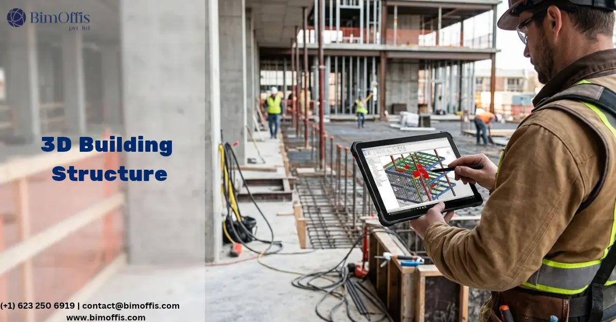
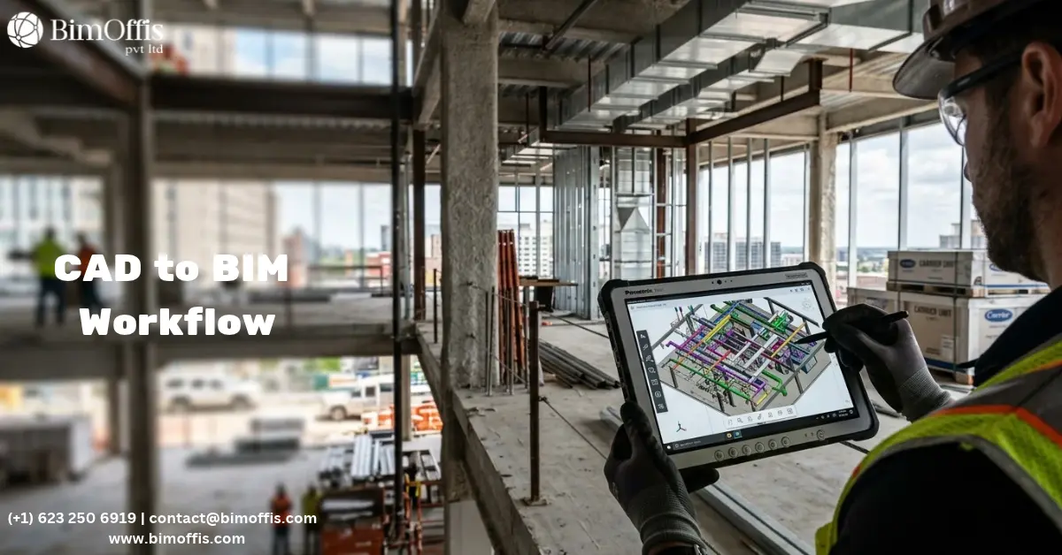
BIM-based detailing places every steel member in a three-dimensional model. That model coordinates against the architectural and MEP models before fabrication begins, so conflict checks between structural steel and other building systems happen digitally, not on site.
For example, picture a structural member that would have clashed with a main mechanical duct run. In this case, coordination repositions it before the shop drawing gets produced. Similarly, take a connection plate that would have needed a MEP penetration through its web: the team redesigns it before fabrication. Overall, fixes like these cost modelling time, not fabrication cost or erection delays.
Drawing Production From the Model
When steel members and connections exist as accurately modelled objects in BIM, teams can generate shop drawings, bolt schedules, weld schedules, and material lists straight from the model. As a result, manual, separate production becomes unnecessary. This keeps the drawings consistent with the coordinated model. So when design changes happen during coordination, the model updates, and the drawings follow it, reflecting the current design rather than an outdated one.
The Bottom Line
Structural steel detailing determines whether the steel coming off the fabrication shop floor fits the structure correctly, connects as the engineer designed, and erects on programme.
Ultimately, good detailing gives the fabricator documentation to work from with confidence and gives the erection team drawings they can assemble efficiently. Every connection sits correctly configured. Every dimension stays consistent. And every non-standard condition gets an explicit detail that resolves it.
In the end, steel structures that erect efficiently, connect correctly, and hit the agreed programme almost always share one thing: a team that detailed the steel thoroughly, reviewed it rigorously, and coordinated it carefully before fabrication began. That’s what good structural steel detailing makes possible.
Improve fabrication accuracy with professional structural steel detailing services that support precise connections, clear drawings, and efficient on-site assembly.
Frequently Asked Questions from Clients
What is structural steel detailing?
Structural steel detailing converts structural designs into fabrication drawings, connection details, and erection documentation.
What do structural steel detailing drawings include?
They include general arrangement drawings, individual member drawings, connection details, erection drawings, bolt schedules, and weld schedules.
Why is structural steel detailing important?
Accurate detailing helps steel members fit correctly, reduces fabrication errors, prevents costly site modifications, and supports efficient erection.
What are connection details in structural steel detailing?
Connection details define the exact configuration, dimensions, bolts, welds, components, edge distances, and spacings required for structural connections.
How does BIM improve structural steel detailing?
BIM places steel members in a coordinated 3D model, helping teams identify clashes with architectural and MEP systems before fabrication.
How does the detailing review process reduce project costs?
Reviewing shop drawings before fabrication helps identify design interpretation or connection issues early, when corrections require drawing revisions rather than costly steel rework.