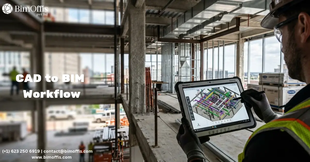
CAD to BIM conversion takes existing 2D CAD drawings and transforms them into intelligent three-dimensional BIM models. As a result, these models can coordinate, document, and serve a building project in ways that flat drawings simply cannot.
Let me start with something that architecture firms, engineering consultants, and contractors all encounter regularly.
A project comes in that involves an existing building. The existing documentation is a set of CAD drawings from the original construction or a previous renovation. Typically, the design team needs these drawings as the basis for new design work. The CAD drawings show the building layout, the structural system, the MEP routes, and the spatial organisation. However, they do not show any of the intelligence that a BIM model carries. In the CAD drawing, the walls are just lines, and they do not know they are walls. They carry no fire rating, no thermal performance, and no acoustic specification. Similarly, the MEP systems in the CAD drawing are only lines and symbols. Because of this, they cannot participate in clash detection, generate schedules, or coordinate automatically with other systems.
CAD to BIM conversion turns those lines and symbols into intelligent BIM objects that do all of these things. For example, the walls become Revit wall objects with correct layer compositions and material properties, while the MEP systems become correctly classified system objects with appropriate connector types and performance parameters. Consequently, the building stops being a collection of drawings and becomes a coordinated digital model that serves the project throughout its lifecycle.
Why CAD to BIM Conversion Matters
The Limitations of Working From CAD Drawings
Working from CAD drawings as the basis for design development creates limitations, and these limitations compound as the project progresses.
First, CAD drawings are static. When the design changes, every affected drawing needs manual updating. On a large project with hundreds of drawing sheets, this manual process consistently produces inconsistencies between sheets, and these inconsistencies become sources of contractor queries, variation claims, and construction errors. For instance, the floor plan might show the current design while the section shows something from three weeks ago, and the door schedule may not reflect changes made after the last design review.
Second, CAD drawings are two-dimensional. They show what the design looks like in plan, section, and elevation, but they cannot show whether the design actually works in three dimensions. A structural beam might conflict with the main ductwork run, yet overlaid CAD drawings hide this conflict until installation reveals it.
Finally, CAD drawings carry no data. They cannot generate schedules or drive quantity takeoffs, nor can they tell facilities management what is installed and where. As a result, a building that exists only as CAD drawings has documentation that cannot participate in the intelligent workflows that modern construction and facilities management increasingly depend on.
What BIM Adds to the Same Information
When the same information moves from CAD drawings into a BIM model, all of these limitations disappear.
For one thing, the BIM model generates documentation automatically from the model itself, so it does not require manual maintenance of separate drawing sheets. Therefore, when the design changes, every view and schedule that shows the changed element updates automatically. The floor plan, the section, and the door schedule all reflect the current design because they all come from the same source.
In addition, the BIM model exists in three dimensions. Teams can federate the structural and MEP systems that share the same building space in a coordination environment and check them for conflicts automatically. As a result, automated clash detection consistently catches coordination failures that traditional drawing-based processes miss, and it catches them before they reach the construction site.
Finally, the BIM model carries data. Every element carries the information the project needs to manage it, specify it, cost it, install it, and maintain it, so that data supports workflows that drawings simply cannot serve.
How CAD to BIM Conversion Works in Practice
From Static Lines to Intelligent Objects
The CAD to BIM conversion process starts with understanding the existing CAD drawings well enough to build an accurate BIM model from them.
This understanding is not automatic. CAD drawings contain lines, arcs, and text that represent building elements, but the conversion process requires someone who understands what each element represents and how to model it correctly in the BIM environment. For example, a line in a CAD drawing might represent a wall, a structural element, an MEP system component, or a dimension line. So the person doing the conversion needs to know which is which and how to model each one correctly.
For architectural elements, walls become Revit wall objects built with the correct wall type for the construction they represent. Meanwhile, doors and windows become parametric Revit families with the correct dimensions and specifications. Ceilings become ceiling objects with the correct material and height parameters, and floors become floor objects with the correct structural and finish layer compositions.
For structural elements, columns and beams become correctly profiled structural families with the correct material grade parameters. Similarly, foundations become correctly configured foundation families at the correct levels, and connections between structural elements get modeled at the level of detail the project requires.
For MEP elements, the lines and symbols representing ductwork, pipework, cable trays, and equipment become correctly classified MEP system objects. Each one carries the correct connector types, system classifications, and performance parameters.
LOD Decisions in CAD to BIM Conversion
The level of development at which elements get modeled depends on what the model will be used for. For instance, a model built as the existing conditions reference for a renovation project needs enough accuracy to coordinate the new design against the existing building. However, it does not necessarily need every element modeled at the highest possible LOD.
Good practice defines the LOD requirements for each element category before modeling begins. Structural elements that the new design needs to coordinate against closely get modeled at higher LOD, while architectural finishes in areas the renovation will not affect get modeled at lower LOD. This selective approach produces a model that serves the project without consuming more time and budget than the project actually needs.
Quality Checking the Converted Model
Every CAD to BIM conversion project needs systematic quality checking before the team uses the converted model as the basis for new design work.
The quality check verifies that elements in the BIM model match what the CAD drawings show. Specifically, wall positions, structural element locations, and MEP system routes in the model must align with their drawn positions within the tolerances the project requires. It also verifies that element types are correct: walls have the right construction types, structural elements have the right profiles, and MEP elements have the right system classifications.
Additionally, the quality check verifies that the model is internally consistent, with no modeling errors that would produce incorrect documentation or misleading coordination results. Consider a wall that is modeled correctly in plan but whose height does not reach the floor above; this creates a gap in the building envelope that would not exist in the real building. Catching these errors early therefore prevents design mistakes that would otherwise follow from working against incorrect existing conditions information.
Where CAD to BIM Conversion Delivers the Most Value
Renovation and Refurbishment Projects
CAD to BIM conversion delivers its highest value on renovation and refurbishment projects, where the existing CAD documentation needs to become the foundation for new design work.
Once the existing building exists as a BIM model, the design team can develop the new design directly within that model. The new walls, MEP systems, and structural elements all coordinate automatically against the existing building elements in the same model environment. Consequently, conflicts between the new design and existing conditions appear during coordination rather than on site, and the renovation design rests on an accurate, intelligent record of the existing building rather than on static drawings that require interpretation.
Moreover, CAD to BIM conversion often reveals discrepancies between the CAD drawings and the actual building, discrepancies that traditional design-from-drawings workflows would have missed until construction uncovered them. For example, elements shown in the drawings might not exist in the real building, or elements in the real building might not appear in the drawings at all. These issues surface during conversion, so the design team can address them in the design rather than on site.
Projects Requiring BIM Deliverables From Existing Documentation
Many projects now require BIM deliverables but involve existing buildings that were documented in CAD before BIM became a project requirement. In these cases, CAD to BIM conversion creates the BIM deliverable from that existing CAD documentation.
For example, public sector projects often make BIM a contractual requirement, while building owners often specify BIM deliverables for facilities management purposes. Likewise, many design teams’ BIM workflows require an existing conditions BIM model rather than CAD drawings. In each case, CAD to BIM conversion produces the BIM starting point the project needs.
The Bottom Line
CAD to BIM conversion streamlines design and construction workflows. Essentially, it replaces the limitations of static 2D CAD documentation with the intelligence, coordination capability, and data richness of a properly built BIM model.
As a result, the design team works from a model rather than drawings, with all the coordination, documentation, and data management benefits that entails. The construction team, in turn, gets coordinated documentation that derives from a model checked in three dimensions rather than assumed to work. Meanwhile, the facilities management team gets an as-built record that carries the information they need to manage the building, rather than a collection of drawing sheets that require interpretation.
That is what CAD to BIM conversion makes possible. So on any project where the limitations of working from CAD drawings affect design quality, coordination reliability, or facilities management effectiveness, the investment in conversion is worth making.
Streamline project workflows with professional CAD to BIM services that improve design coordination, model accuracy, documentation, and construction planning.
Frequently Asked Questions from Clients
What is CAD to BIM conversion?
CAD to BIM conversion transforms existing 2D CAD drawings into intelligent 3D BIM models.
Why is CAD to BIM conversion important?
It improves design coordination, documentation, clash detection, and data management compared with static CAD drawings.
What elements can be converted from CAD to BIM?
Walls, doors, windows, ceilings, floors, structural elements, ductwork, pipework, cable trays, and MEP equipment can be modeled.
How does CAD to BIM support renovation projects?
It creates an intelligent existing-conditions model that helps teams coordinate new designs with the existing building.
What is the role of LOD in CAD to BIM conversion?
LOD determines the required level of detail for each element based on how the BIM model will be used.
How is the converted BIM model quality checked?
Quality checks verify element locations, types, system classifications, model accuracy, and internal consistency against the CAD drawings.