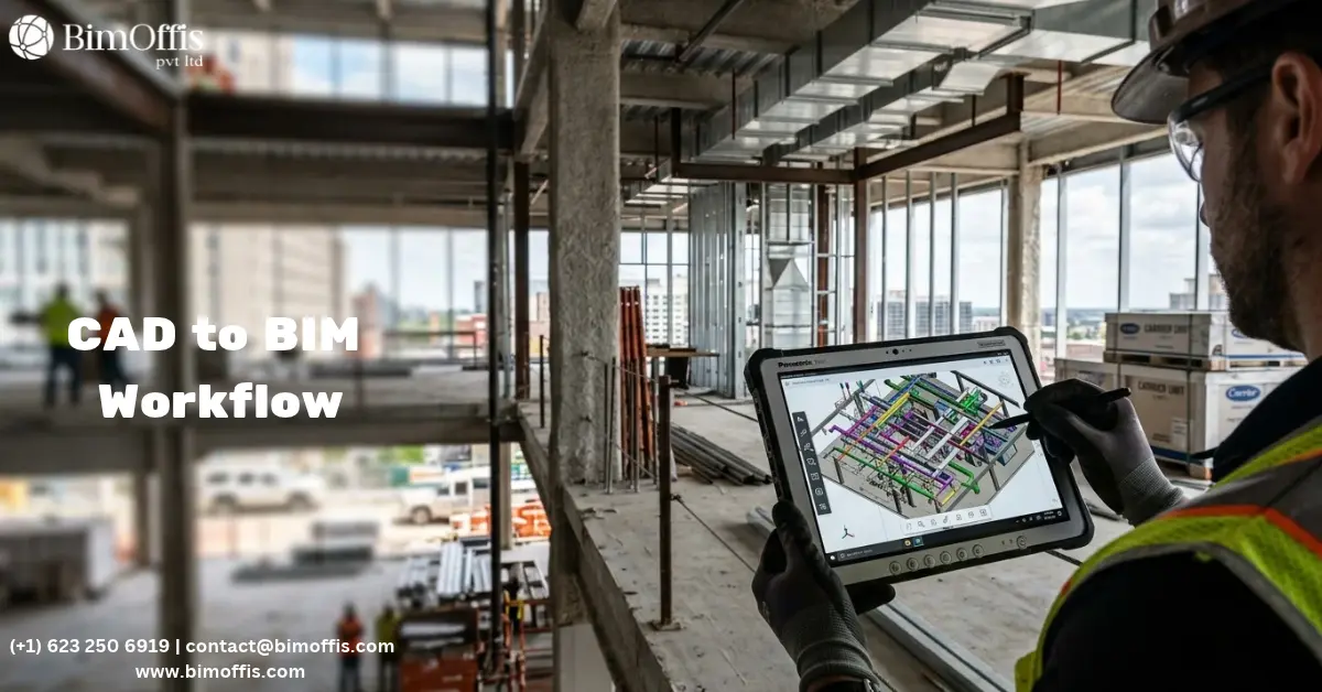
Electrical modeling in BIM takes an electrical design from a 2D drawing exercise into a three-dimensional coordinated process. Teams find conflicts during design instead of on site. They plan installation against real geometry. Documentation comes straight from a model that reflects the current coordinated design.
Electrical engineers, MEP coordinators, and project managers all recognise the problem this solves.
Why Electrical Systems Need 3D Coordination
Electrical systems in a modern building are extensive. Cable trays carry power distribution from the main switchroom to every sub-distribution board on every floor. Conduits run through walls and above ceilings to every outlet, fitting, and piece of equipment. Containment systems separate high voltage from low voltage, power from data, and general power from emergency circuits. Panel rooms, riser shafts, and plant spaces house the distribution equipment.
All of this infrastructure needs space, routing paths, and clearances for installation and maintenance. It also needs to coexist with every other building system competing for the same spaces.
In a 2D design environment, coordinating this against structural elements, mechanical ductwork, plumbing pipework, and fire protection systems relies on drawing overlay and manual checking. Some conflicts get caught. Many get missed, because they only exist in three dimensions and a 2D overlay can’t reveal them. Missed conflicts show up on site as stopped work, rerouted cable trays, and programme delays, and those cost far more to fix than electrical modeling would have cost to prevent them.
Electrical modeling in BIM solves this by putting the complete electrical design in the same three-dimensional coordinated environment as every other building system, before any installation begins.
What Electrical Modeling in BIM Actually Covers
The Complete Electrical System as Intelligent 3D Objects
Electrical modeling in a BIM environment covers every element of the electrical system as accurately dimensioned three-dimensional objects, rather than as schematic lines on a 2D plan.
Cable tray systems exist in the model at their actual installed dimensions. Every tray section appears at its actual width and depth, and every tray run follows its actual routing path through the ceiling void, the riser shaft, and the plant room. Every fitting, bend, tee, and reducer sits at its actual position and configuration. Support systems that fix the trays to the structure also appear at their real positions and dimensions, claiming the same space in the ceiling void that they occupy on site.
Conduit systems follow their actual routing paths through walls, floors, and ceilings, rather than appearing as schematic lines that only suggest routing. Specific conduit sizes appear at their actual diameters, including conduit banks where multiple conduits share a routing path. Where conduits penetrate structural or fire-rated elements, the penetration positions and sizes appear in the electrical model, so coordination with structural and fire protection requirements can happen during design.
Distribution boards, switchboards, and panel equipment appear at their actual dimensional footprints, with the correct clearance zones that installation and maintenance require. Cable entry and exit routes for every panel also appear in the model, so teams can coordinate the routing of cables to the distribution system and load circuits against the available space and the other services sharing it.
Luminaires, emergency lights, and exit signs appear at their actual installed positions with the correct mounting configuration for each fitting type. The relationship between the lighting layout and the reflected ceiling plan is clear in the coordinated model, so teams can confirm lighting positions against the ceiling grid before ceiling installation begins.
How Electrical Modeling Improves Design Coordination
Three-Dimensional Coordination That 2D Cannot Achieve
Electrical modeling’s biggest contribution to design coordination is simple: it lets teams check the electrical design against every other building system in three dimensions at once.
When the electrical model sits in the same federated coordination environment as the structural, architectural, mechanical, plumbing, and fire protection models, automated clash detection checks every electrical element against every other element in the building. Every geometric conflict gets flagged, not just the conflicts visible in a plan-view overlay, but every three-dimensional conflict, regardless of where it sits or how subtle it looks in any single view.
A cable tray that clears a structural beam in plan but clips its bottom flange in section shows up as a clash. A conduit that routes through a structural wall in a position that conflicts with the reinforcement shows up as a clash requiring either engineering approval for a penetration or a reroute. A distribution board that blocks maintenance access to an adjacent mechanical unit shows up as a soft clash that needs resolving before both pieces of equipment lock into their modeled positions.
Resolving each of these conflicts during design costs a model update and a coordination conversation. Resolving the same conflicts during construction costs programme delay, rework, and variation claims. On complex projects, where electrical system density makes coordination failures numerous rather than occasional, the accumulated savings consistently justify the electrical modeling investment.
Coordinating Cable Separation Requirements
Electrical systems carry separation requirements between cable categories that traditional 2D coordination handles poorly. High voltage and low voltage cables need physical separation. Power cables and data cables need separation to prevent electromagnetic interference. General power circuits need separation from emergency circuits, to protect life safety systems from failures in the general power distribution.
Electrical modeling lets teams check these separation requirements against the coordinated model, rather than assume they’ll work out on site. When cable tray routes for different cable categories sit in the model at their actual positions, teams can measure the separation distances directly and confirm they meet spec. Wherever the proposed routing can’t achieve the required separation, the model flags a soft clash that forces a redesign before installation locks in.
2D drawing coordination cannot achieve this kind of separation checking reliably, because true separation distances only become verifiable once the runs exist together in the same three-dimensional space.
What Electrical Modeling Delivers for the Construction Phase
Installation Documentation From the Coordinated Model
Once the electrical system exists as an accurately modeled, coordinated BIM model, construction documentation comes directly from that model, instead of from a separate manual drawing exercise.
Cable tray layout drawings, showing tray routes and sizes on each floor, derive from the model with dimensions that reflect the current coordinated design. Panel schedules, listing every distribution board with its location, incoming supply, and circuit assignments, pull straight from the model data. Luminaire schedules, listing every light fitting with its type, circuit reference, and control arrangement, work the same way. When coordination changes a cable tray route or repositions a panel, the documentation updates with the model.
The installation team works from documentation that reflects the current coordinated design, not drawings that predate the last round of changes. This currency cuts down the RFIs that arise from mismatches between drawings and the coordinated design, reduces variation claims from contractors building to outdated information, and eliminates rework caused by documentation errors.
Supporting Prefabrication
Electrical modeling also supports off-site prefabrication of electrical assemblies in ways 2D coordination can’t reliably enable.
Once cable tray routes exist as accurately coordinated three-dimensional geometry, teams can prefabricate sections of cable tray off-site to the dimensions the model specifies. Those sections arrive on site and install straight into their coordinated positions, without field adjustment. Where panel assemblies exist in the model with their actual cable entry configurations, teams can prefabricate the cable management assemblies that organise the cables entering each panel to that specific configuration.
Prefabrication reliability depends entirely on modeling accuracy. An accurate model produces prefabricated assemblies that fit. An approximate model forces field modification, which erases the efficiency gain prefabrication was supposed to deliver.
Where Electrical Modeling Delivers the Most Coordination Value
Healthcare Facilities
Healthcare buildings carry electrical infrastructure at a density and regulatory complexity that makes electrical modeling genuinely necessary, not just beneficial. Operating theatres, intensive care units, and imaging suites pack general power, medical equipment power, emergency power, lighting, and data infrastructure into the same ceiling zones. Regulatory requirements for healthcare electrical systems add further layers of specification complexity, which makes rigorous electrical modeling essential.
Data Centers
Data centers combine the highest electrical system density with the most demanding commissioning timelines in the industry. Redundant power distribution, UPS systems, power distribution units, bus ducts, and structured cabling all interact in environments where coordination failures discovered during commissioning threaten the project go-live date. Every serious data center project team treats electrical modeling as non-negotiable.
Large Commercial and Mixed-Use Developments
Large commercial office buildings, mixed-use developments, and high-rise residential projects carry electrical systems complex enough that modeling consistently pays for itself in coordination value. The documentation accuracy it produces also reduces procurement errors and site queries throughout construction.
The Bottom Line
Electrical modeling in BIM improves design coordination by keeping the electrical design where it needs to be throughout the process: in the same three-dimensional coordinated environment as every other building system, checked systematically for conflicts, and used as the source that construction documentation and prefabrication draw from.
Projects that consistently deliver electrical installations that fit the available space, follow the planned sequence, and commission without surprises share one trait, they invest in electrical modeling properly, from early design development through to construction handover.
That’s what good electrical modeling delivers. On any project where electrical system density makes coordination failures likely and expensive, investing in it properly is one of the most direct ways to protect both the programme and the budget.
Improve electrical design coordination with professional 3D BIM electrical modeling services that help identify clashes, refine layouts, and support accurate installation.
Frequently Asked Questions from Clients
What is electrical modeling in BIM?
Electrical modeling in BIM creates accurate 3D representations of electrical systems in a coordinated digital environment.
What does 3D BIM electrical modeling include?
It includes cable trays, conduits, distribution boards, switchboards, panels, luminaires, emergency lights, and exit signs.
How does electrical modeling improve design coordination?
It allows teams to coordinate electrical systems with structural, architectural, mechanical, plumbing, and fire protection elements in 3D.
How does BIM electrical modeling support clash detection?
It identifies three-dimensional conflicts such as cable tray, conduit, structural, and equipment clashes before construction.
How does electrical modeling support construction documentation?
Cable tray layouts, panel schedules, and luminaire schedules can be generated directly from the coordinated BIM model.
Can electrical BIM modeling support prefabrication?
Yes, accurate 3D geometry can support off-site prefabrication of cable tray sections and electrical assemblies.