Scan to BIM sounds simple when you first hear about it. You scan a building, turn the scan into a model, and use the model.
In practice, it involves a lot more than that. Teams that treat it as simple often end up with a model that looked impressive at delivery. But it turns out to be difficult to use for its intended purpose.
Let me walk through the workflow, step by step, and explain what matters at each stage.
Step One: Define What the Model Needs to Do
Start Here, Not at the Scanner
I want to be direct about something. Skipping this step causes the most common disappointment in scan to BIM projects. Scanning is the exciting part. It involves technology on site and produces fast results. So teams rush to get there.
But scanning without a clear model scope creates problems. The data either captures too little to be useful, or too much to process efficiently. Sometimes it does both, depending on which part of the building you look at.
Before anyone picks up a scanner, the project needs clear answers to three questions. What does this model actually need to do? Which building systems and elements need capturing? And at what level of detail does each element need modeling?
A model for space planning needs different things than one for MEP retrofit coordination. Structural assessment models need different LOD decisions than architectural renovation models. Getting this clarity before scanning begins determines everything downstream. It shapes the scanner positions you need, the resolution settings that suit the project, and what the modelers must produce from the data.
Do this step properly. The rest of the workflow becomes far more straightforward.
Step Two: Plan and Execute the Laser Scan
What Good Scanning Actually Looks Like
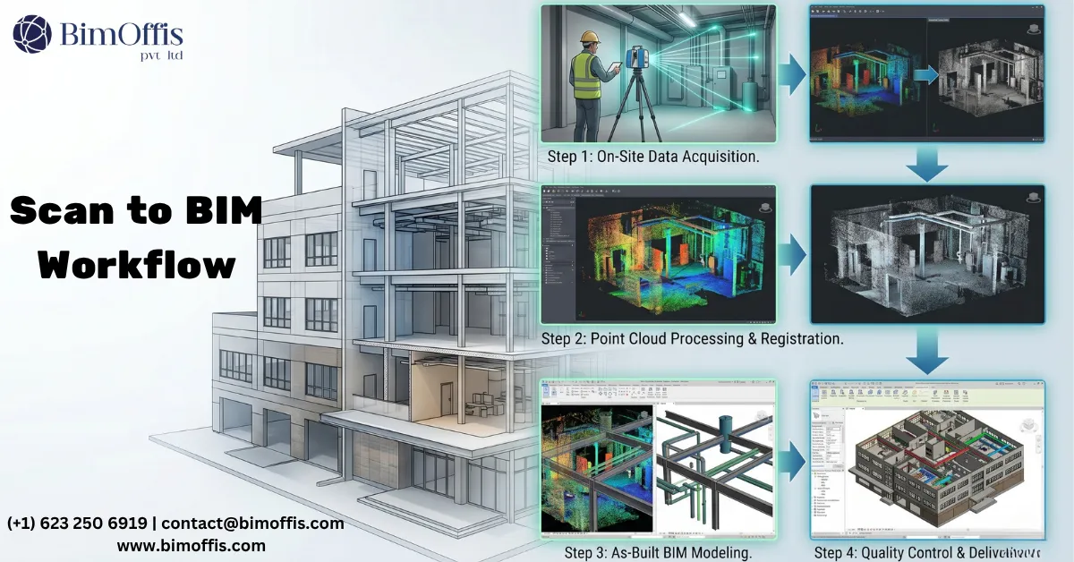
With scope defined, the scanning team plans its positions. These need to cover every area within scope with sufficient data density. The team sets resolution to match what the model requires. They also work out how scanner positions will connect once the data gets processed.
The scanning itself moves quickly. A modern laser scanner captures millions of data points per second. Scanning a large commercial floor plate might take a few hours, while a multi-storey building might take a few days. The scanner also captures photographic data at each position, and this colour information makes the point cloud far more readable during modeling.
Good scanning coverage means every area within scope appears in the point cloud with enough density. Modelers can then identify and accurately model every required element. Coverage like this also means scanner positions overlap enough with each other, which allows accurate registration later.
Poor coverage leaves shadow zones, areas the scanner could not see because something blocked the line of sight. These show up as holes in the point cloud. Elements in these zones cannot come from the scan data at all, and the model ends up with gaps precisely where the project might need it most.
Step Three: Register and Process the Point Cloud
Turning Raw Data Into Something Usable
The raw output from scanning is a collection of separate point clouds, one from each scanner position. Registration software combines these into a single unified dataset representing the complete scanned environment.
This software aligns adjacent scanner positions using their overlapping data. Modern software handles most of this automatically. However, the result still needs a manual check. Registration errors are subtle, and they propagate through the entire model once modeling builds on the registered data. Catching an error before modeling starts costs a few hours. Discovering it after the model is half built costs far more.
Once registration is complete, the point cloud needs cleaning. The scanner captures everything in its field of view, including people who walked through the scan, temporary equipment on site, and anything else present during the session. The processing stage removes these elements. The team then structures and formats the cleaned point cloud for import into the BIM platform, since different platforms handle point cloud data differently.
Step Four: Build the Model From the Point Cloud
Where the Real Skill Lives
This step determines whether the project gets a genuinely useful model or just visually convincing geometry.
Modelers work inside the BIM platform with the point cloud as their reference. They build the model element by element from what the scan shows. Importantly, this is not a tracing exercise. Walls need modeling with correct layer structures, not just as solid shapes matching the scan outline. Structural elements need correct profiles and material grades. MEP systems need modeling as intelligent objects with correct system classifications and connector types, rather than as generic geometry that happens to sit in the right position.
This distinction matters enormously for what the model can actually do. A model that is geometrically accurate but intelligently hollow cannot generate a reliable schedule. It cannot support proper clash detection. It cannot serve facilities management in any meaningful way. Good scan to BIM modeling produces elements that behave correctly in every workflow the model needs to support, not just elements that look right in a 3D view.
The scope definition from Step One drives every LOD decision at this stage. Elements within scope receive the level of detail the scope requires. Elements outside scope either get excluded or noted at a lower LOD. Where the scan reveals discrepancies between the building and the original design drawings, good practice documents them rather than resolving them arbitrarily, the client needs to know about them.
Step Five: Check the Model Against the Point Cloud
Do Not Skip This
An unchecked scan to BIM model carries unknown accuracy. The modeler may have traced elements correctly. Or they may have made judgment calls that introduced errors. Without a quality check, neither side knows which.
Checking involves returning to the point cloud. The team verifies that significant elements in the model align with the scan data, within the tolerances the project requires. Elements that fall outside tolerance get corrected before delivery. The quality check also reviews completeness against the scope definition, every element within scope should appear in the model at the specified LOD. The team identifies and addresses any gaps before the model leaves their hands.
Step Six: Deliver and Integrate the Model
Getting the Value Out
The delivered model needs the correct format and structure for its intended workflows. Facilities management models need different data organisation than renovation design models. Structural assessment models need different element classifications than space planning models.
Good delivery also includes documentation that helps the team use the model correctly. This covers notes on scanning coverage, flagged discrepancies between the scan and original drawings, LOD information for each element category, and any limitations the client should understand before working from it.
How well the model gets woven into the project workflow determines how much value the project actually captures. A model that sits on a file server, disconnected from its intended workflows, delivers nothing, no matter how accurately the team built it.
The Bottom Line
The scan to BIM workflow creates value at every step, not just in scanning and modeling. Scope definition decides whether the model will serve the project. Scanning quality decides whether the data is complete. Registration accuracy decides whether the point cloud is reliable. Modeling quality decides whether the model is genuinely intelligent or just geometric. Quality checking decides whether the model is accurate enough to trust.
Getting each step right separates a scan to BIM deliverable that genuinely changes how a project team works from one that was impressive to produce and disappointing to use.
Transform your point cloud data into accurate BIM models by working with our Scan to BIM experts for your next project.
Frequently Asked Questions from Clients
What is the Laser Scan to BIM Workflow?
It is the process of converting laser scan data into an accurate BIM model.
What is the first step in the Scan to BIM workflow?
The process starts with capturing existing conditions using 3D laser scanning.
What is a point cloud in Scan to BIM?
A point cloud is a collection of scanned data points used to create BIM models.
Which software is used in the Laser Scan to BIM workflow?
Revit, Autodesk Recap, and Navisworks are commonly used.
Which projects benefit from Laser Scan to BIM?
Renovation, restoration, retrofit, and facility management projects.
Why is the Scan to BIM workflow important?
It improves accuracy, reduces rework, and enhances project coordination.