A construction document set is the complete technical package that takes a building project from approved design to physical construction. It is the bridge between what the design team intended and what the contractor actually builds. And the quality of that bridge determines almost everything about how smoothly the construction phase runs.
Let me start with something that experienced project managers and architects know well but that clients and newer practitioners sometimes underestimate.
A poorly prepared construction document set does not just create inconvenience. It creates disputes. Ambiguities in the documents become potential change orders. Conflicts between drawings and specifications become potential claims. Furthermore, every condition the documents fail to address becomes a decision made on site by someone without the design intent knowledge to make it correctly.
A properly prepared construction document set, on the other hand, gives the contractor everything they need to price accurately, procure correctly, and build what was designed. Understanding what a complete construction document set actually contains is therefore the foundation of understanding why document quality matters so much.
Architectural Drawings
The Core of Any Construction Document Set
Architectural drawings form the foundation of every construction document set. They describe the building spatially and aesthetically, defining what it looks like, how it is organised, and how every space relates to every other space.
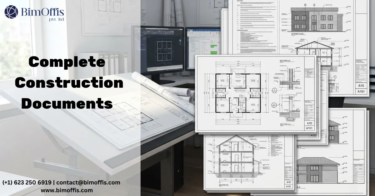
A complete set of architectural drawings covers the building at multiple scales. Floor plans show the complete layout of every level, with dimensions, room names, and door and window locations. Reflected ceiling plans show ceiling heights, ceiling materials, and the positions of ceiling-mounted elements. These include lighting, HVAC grilles, and any other ceiling-integrated systems.
Furthermore, exterior elevations show every face of the building at a scale sufficient to communicate the facade design, window and door positions, and material boundaries. Building sections cut through the building vertically to show how it works at key cross-sections. They demonstrate floor-to-floor heights, structural relationships, and the vertical organisation of spaces.
Details and Schedules
Large-scale detail drawings show how specific architectural conditions work at the level of precision required for construction. Standard architectural details cover typical wall junctions, window and door conditions, floor transitions, and ceiling terminations. Non-standard details address the specific conditions of the project that do not follow standard practice. Consequently, these details prevent incorrect interpretation on site.
Door and window schedules list every door and window in the project with their dimensions, types, hardware specifications, and any performance requirements. Room finish schedules specify the floor, wall, and ceiling finishes for every space, referencing the material specifications in the project specification document.
Structural Drawings
Defining the Building’s Structural System
Structural drawings define the complete structural system that holds the building up and transfers loads to the ground. A complete structural drawing set covers foundations, structural framing at every level, connections, and any specialist structural elements the project requires.
Foundation drawings show the type, size, depth, and reinforcement of every foundation element. Framing plans show the structural layout at each floor level, indicating beam and column positions, sizes, and orientations. Additionally, structural sections and details show how structural elements connect to each other and to the architectural elements they support.
Moreover, structural drawings need to coordinate with architectural drawings. Structural beam depths must be consistent with the ceiling heights the architecture requires. Column positions must align with the architectural layout rather than conflicting with it. A construction document set where the structural and architectural drawings contradict each other therefore creates coordination problems on site that are expensive to resolve.
MEP Drawings
Mechanical, Electrical, and Plumbing Systems
MEP drawings cover the building’s operational infrastructure. They are where the majority of construction coordination complexity lives and, consequently, where poorly coordinated construction document sets create the most expensive site problems.
Mechanical systems need drawings covering HVAC including air handling units, ductwork distribution, terminal units, and controls. These show equipment locations, duct routes, and the connections between system components at the level of detail required for installation and commissioning.
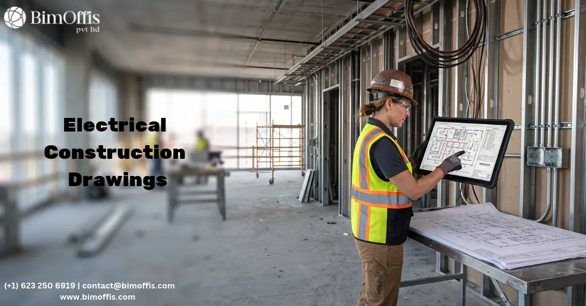
Electrical systems, on the other hand, need drawings covering power distribution from incoming supply through to final circuits, lighting layouts, cable tray and conduit routing, and panel locations. Furthermore, these drawings need to coordinate against the structural and architectural drawings. This ensures that cable tray routes, conduit paths, and equipment positions do not conflict with structural elements or architectural features.
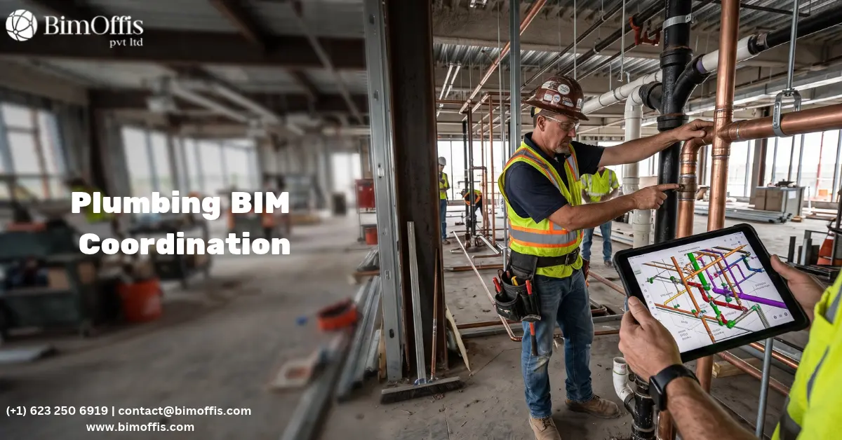
Plumbing and fire protection systems also need comprehensive drawing coverage. Plumbing drawings show pipe routes, fixture locations, equipment positions, and the connections between system components. Additionally, fire protection drawings cover sprinkler systems, fire alarm systems, and any other life safety systems the project requires.
Civil and Site Drawings
Everything That Happens Outside the Building
Civil and site drawings cover the work that happens outside the building envelope. They are often underappreciated in the construction document set but they define critical elements of the project. These affect everything from drainage performance to accessibility compliance.
Site plans show the building’s position on the site, setback dimensions, car park layouts, and pedestrian routes. They also show the relationship between the building and the site boundaries. Grading plans show the existing and proposed ground levels across the site, defining how surface water drains away from the building.
Furthermore, civil drawings cover external drainage systems, utilities connections, road and pavement construction, and any retaining structures the site requires. Without complete civil drawings, the interface between the building and its site is left to interpretation. This consistently produces problems at the building perimeter where architectural and civil work must meet.
Specifications
The Written Counterpart to the Drawings
Specifications are the written component of the construction document set. They describe in detail the materials, products, workmanship standards, testing requirements, and inspection procedures that apply to every element of the project.
A well-written specification works alongside the drawings to define the project completely. Where the drawings show what goes where, the specification describes what it needs to consist of, what standard it needs to meet, and how compliance gets demonstrated and verified.
The relationship between the drawings and the specifications is contractual. Both form part of the construction contract. When they conflict, both parties can point to the contract in support of their position. Consequently, ensuring that the drawings and specifications are consistent with each other is one of the most important quality checks in the construction document preparation process.
Schedules and Quantification Documents
Data That Drives Procurement and Construction
Schedules bridge the gap between the drawings and the procurement and construction process. They extract specific information from the drawings and specifications into tabular formats that support ordering, installation, and inspection.
Door schedules list every door with its size, type, fire rating, acoustic performance, hardware, and finish. Window schedules do the same for glazed elements. Room data sheets, moreover, provide a complete picture of the requirements for each space, including finishes, MEP services, and any specialist requirements. Equipment schedules list every piece of mechanical and electrical equipment with its specification, location, and connection requirements.
Furthermore, quantity takeoffs derived from a well-coordinated construction document set give the contractor and the cost manager accurate material quantities for procurement and cost planning. When quantities come from an accurately built BIM model, they update automatically when the design changes. As a result, the cost plan always reflects the current design rather than a version from several weeks ago.
The Bottom Line
A complete construction document set contains architectural drawings, structural drawings, MEP drawings, civil and site drawings, specifications, and schedules. Each component serves a specific purpose and each one needs to be complete, accurate, and consistent with every other component.
The construction projects that deliver what was designed, on programme and within budget, are almost universally the ones where the construction document set was prepared to a high standard. Document gaps become site problems. Component conflicts become disputes. Ambiguities become decisions made without the design intent knowledge to make them correctly.
Getting the construction document set right is therefore not a documentation exercise that happens after the real design work is done. It is, ultimately, a fundamental part of delivering a project properly.
Avoid costly documentation errors by working with our BIM documentation experts to create accurate construction document sets.
Frequently Asked Questions from Clients
What is a Construction Document Set?
A Construction Document Set contains all drawings and specifications needed for construction.
What is included in a Construction Document Set?
It includes architectural, structural, MEP, site, and detail drawings with specifications.
Why are Construction Document Sets important?
They guide construction, reduce errors, and improve project coordination.
Who prepares Construction Document Sets?
Architects, engineers, and BIM professionals prepare these documents.
How does BIM improve Construction Documentation?
BIM creates coordinated, accurate, and up-to-date construction documents.
Which projects require Construction Document Sets?
Residential, commercial, industrial, healthcare, and infrastructure projects.