Electrical BIM coordination on complex building projects is one of those things that looks optional until you have lived through a project where it did not happen properly. Then it looks essential.
Let me describe something that plays out on complex building projects with uncomfortable frequency.
The electrical contractor arrives on site ready to begin cable tray installation on a large commercial floor plate. The route the electrical drawings show is clear on the plan. On site, however, that route runs directly through structural steelwork the coordination drawings never resolved. The mechanical contractor installed ductwork last week. It now occupies a significant portion of the ceiling void the electrical cable trays were supposed to share.
Work stops. The electrical contractor needs a redesigned route. The redesigned route affects the mechanical contractor’s installation. A coordination meeting happens on site under time pressure with trades standing by. The resolution takes days rather than hours. The programme slips. Change orders follow.
That situation is preventable. Electrical BIM coordination is how you prevent it.
What Electrical BIM Coordination Actually Is
Electrical BIM coordination means placing the electrical design into a shared three-dimensional coordination environment alongside every other building discipline and running systematic coordination checks before construction begins.
It is not simply producing a 3D model of the electrical design. Furthermore, it is not overlaying electrical drawings on structural drawings and checking for obvious conflicts. It is a process where the electrical model coordinates against the structural model, the architectural model, and every MEP discipline model simultaneously. The electrical model itself must be built to represent the actual installed geometry of cable trays, conduits, panels, and equipment at their real positions and real dimensions.
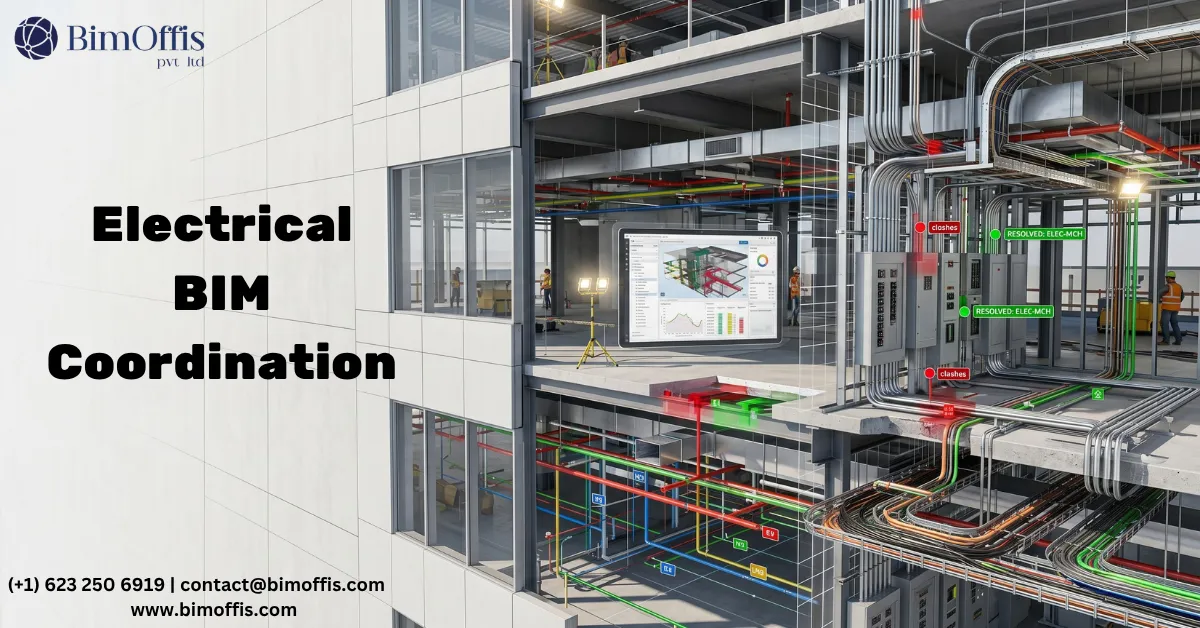
Automated clash detection then checks every electrical element against every other element in the coordinated model. Every conflict, not just the ones visible on a 2D overlay, gets flagged. The coordination team reviews these clashes, the relevant disciplines resolve them collaboratively, and the resolution happens in the model during design rather than on site during construction.
Why Electrical Coordination Is Particularly Complex
The Ceiling Void Competition
On any complex commercial building floor plate, the ceiling void carries more competing infrastructure than most people appreciate from looking at a finished building. Structural beams claim portions of it. Mechanical ductwork, plumbing pipework, and sprinkler systems all compete for the remaining space. Data cabling threads through whatever gaps remain. Electrical cable trays, conduits, and lighting infrastructure need to fit through what is left after everything else has taken its share.
Every system in that ceiling void has specific clearance requirements. Cable trays need maintenance access space above them. High voltage and low voltage systems need spatial separation. Conduits need separation from other services for safety reasons. Furthermore, the electrical systems interact with every other system in ways that produce conflicts when coordination does not happen rigorously throughout design development.
The Density of Electrical Infrastructure
Complex building projects carry electrical infrastructure at a density that makes electrical BIM coordination genuinely challenging. A large commercial office tower might have dozens of electrical risers, hundreds of panel locations, and thousands of metres of cable tray. On healthcare projects, that density increases further. On data centers, it reaches levels that make traditional coordination methods entirely inadequate.
Consequently, coordinating this infrastructure against the rest of the building systems through 2D drawing overlay and manual checking is not just difficult. It is reliably inadequate for buildings of this complexity.
How Electrical BIM Coordination Works in Practice
Building the Electrical Model
Effective electrical BIM coordination starts with an electrical model built to accurately represent the installed geometry of every electrical element. Cable trays need modeling at their actual dimensions, not as schematic lines. Rather than approximating their routes, conduits must follow their actual paths through walls, ceilings, and structural elements. Furthermore, equipment positioning needs to reflect actual installed locations with correct dimensional footprints and required clearances.
This level of modeling accuracy is what makes the clash detection meaningful. A cable tray family that understates the actual width of the tray it represents will miss real conflicts in the installed condition. Moreover, an equipment family that does not represent the actual access clearances will miss spatial conflicts that only become apparent when someone tries to carry out maintenance on the installed equipment.
Federated Model Coordination
Once the electrical model accurately represents the installed electrical infrastructure, the coordination team federates it with the other discipline models in the shared coordination environment. Every discipline model sits in the same three-dimensional space simultaneously. Automated clash detection then runs across every combination of disciplines at once.
The electrical team reviews the flagged clashes, assesses each one, and works with the affected disciplines to resolve them. Furthermore, the coordination process runs in regular cycles throughout design development rather than as a single check before construction documents go out.
Resolving Clashes During Design
The resolution of electrical coordination clashes during design development is where the financial value of electrical BIM coordination is most directly generated. Every clash resolved in the coordination model is a conflict that does not show up on site as a programme delay and a change order.
The cost difference between resolving a coordination conflict during a design meeting and resolving the same conflict on site is significant. On complex projects where system density makes coordination conflicts numerous rather than exceptional, the accumulated value of those avoided site conflicts consistently justifies the electrical BIM coordination investment many times over.
What Good Electrical BIM Coordination Delivers
Coordinated Installation Sequences
When electrical BIM coordination happens properly, the installation sequence for the electrical works can be planned against real coordinated geometry. The electrical contractor knows exactly where other trades will be working and what clearances are available in each zone. They can also plan the installation sequence to allow the electrical works to progress without creating conflicts with other trades.
This coordination of installation sequences is particularly valuable on complex projects where multiple trades work in the same zones simultaneously. Consequently, the site runs more efficiently and the programme stays closer to the original plan.
Documentation That Reflects Coordinated Design
When the electrical design exists as a coordinated BIM model, the documentation supporting procurement and construction comes directly from that model. Panel schedules, cable tray schedules, circuit schedules, and equipment lists all generate from the model automatically. Design changes through coordination trigger automatic schedule updates. The documentation always reflects the current coordinated design rather than a version that existed before the last round of coordination revisions.
For electrical contractors managing procurement against the construction programme, this accuracy has direct financial value.
Prefabrication Support
Electrical BIM coordination enables prefabrication of electrical assemblies in ways that 2D drawing-based coordination cannot support reliably. When cable tray routes exist as accurately coordinated three-dimensional geometry, sections of cable tray can be prefabricated off-site to the exact dimensions the model specifies.
The prefabricated assemblies arrive on site ready to install without requiring adjustment. Furthermore, conduit assemblies can be fabricated to precise lengths and bend configurations. The waste from cutting and adjusting materials on site reduces when accurate model geometry drives the fabrication.
Where Electrical BIM Coordination Matters Most
Data Centers
Data center electrical infrastructure combines the highest system density with the tightest coordination tolerances and the hardest commissioning deadlines in the construction industry. Redundant power distribution, UPS systems, PDUs, bus ducts, and structured cabling all interact in environments where coordination failures discovered during commissioning threaten the project go-live date.
Every serious data center project team treats electrical BIM coordination as a non-negotiable requirement. The alternative is discovering conflicts during installation and commissioning at the worst possible point in the project lifecycle.
Healthcare Facilities
Healthcare buildings carry electrical infrastructure at a density that makes electrical BIM coordination genuinely essential rather than merely beneficial. Theatre suites, intensive care units, and diagnostic imaging facilities have power, lighting, medical equipment power, emergency power, and data infrastructure all competing for the same limited ceiling and wall zones.
The regulatory requirements applying to healthcare electrical systems add layers of coordination complexity. Rigorous electrical BIM coordination is necessary to achieve compliance efficiently.
Large Commercial Developments
Large commercial office buildings, mixed-use developments, and high-rise residential projects all carry electrical systems complex enough that electrical BIM coordination translates directly into smoother installation, fewer site conflicts, and more predictable construction programmes. Moreover, the documentation accuracy it produces reduces procurement errors and site queries throughout the construction phase.
The Bottom Line
Electrical BIM coordination on complex building projects prevents the coordination failures that drive the most avoidable cost and programme risk in electrical installation. Design-stage conflict detection eliminates the programme delays and change orders that site-stage discovery creates. Installation sequencing against coordinated geometry keeps trades working efficiently without blocking each other. Prefabrication becomes reliable when accurate model geometry drives fabrication dimensions. Furthermore, the documentation accuracy the process produces serves procurement, construction, and facilities management consistently throughout the project lifecycle.
For any complex building project where electrical system density makes traditional coordination methods inadequate, electrical BIM coordination is not an enhancement to consider. It is the coordination approach that makes reliable electrical installation achievable.
Ensure seamless electrical coordination from design to installation, Schedule a BIM Consultation.
Frequently Asked Questions from Clients
What is Electrical BIM Coordination?
It is the process of coordinating electrical systems with other building disciplines using BIM.
Why is Electrical BIM Coordination important?
It reduces clashes, improves design accuracy, and streamlines construction.
Which software is used for Electrical BIM Coordination?
Autodesk Revit and Navisworks are commonly used.
How does BIM improve electrical project coordination?
It enables real-time collaboration and early clash detection.
Which projects benefit from Electrical BIM Coordination?
Commercial, residential, healthcare, industrial, and high-rise projects.
What are the benefits of Electrical BIM Coordination?
It improves efficiency, minimizes rework, and supports timely project delivery.