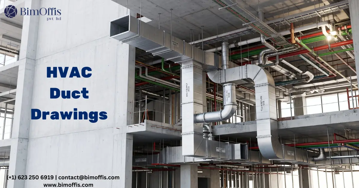
HVAC duct drawings are the bridge between a coordinated BIM model and a fabrication shop that needs to cut, form, and assemble ductwork that actually fits in the building it is going into.
Let me start with something that mechanical contractors and sheet metal fabricators know from direct experience.
A coordinated BIM model is a valuable thing. It shows the ductwork routing, confirms the clearances, and demonstrates that the mechanical design works alongside the structural and MEP systems competing for the same ceiling void. But a BIM model is not a fabrication document. The fabrication shop cannot take a Revit model, open it on the shop floor, and start cutting metal. They need drawings. Specific, dimensioned, coordinated drawings that translate the model geometry into the fabrication instructions the shop actually works from.
That is what HVAC duct drawings do. And when they are produced properly from a well-coordinated BIM model, the result is ductwork that arrives on site and installs in the coordinated positions without adjustment, rerouting, or the kind of field modification that costs more than it should and takes longer than it needs to.
What HVAC Duct Drawings Actually Cover
More Than Layout Plans
HVAC duct drawings produced for fabrication cover significantly more ground than the layout plans that show where ductwork routes through a building. A complete set of fabrication-ready HVAC duct drawings provides every piece of information a sheet metal fabricator and an installation crew need to manufacture and install the system correctly.
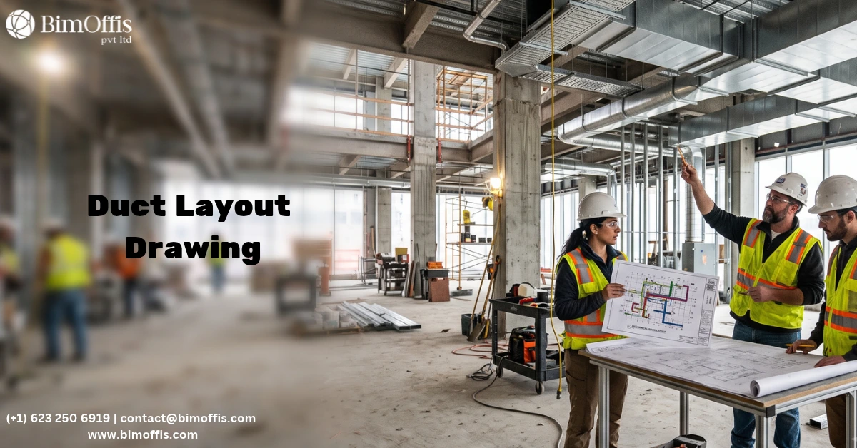
Layout drawings show the ductwork routing on each floor, with dimensions to structure, dimensions to adjacent services, duct sizes, and the positions of all fittings, branches, and equipment connections. These drawings give the installation crew the reference they need to set out the ductwork correctly against the building and coordinate their work with other trades in the same ceiling void.
Duct spool drawings, or fabrication sheets, take sections of ductwork and show every individual piece the fabricator needs to make. The straight sections at their exact lengths. The fittings at their exact dimensions, offset angles, and transition sizes. The connection flanges and their specifications. Furthermore, the spool drawings show how the pieces connect to each other so the fabricator can assemble them correctly before they arrive on site.
Sectional drawings show how ductwork sits in relation to the surrounding building structure, ceiling finishes, and other services at critical locations. These sections confirm the clearances that the coordination model established and give the installation crew the spatial reference they need to hang and support the ductwork correctly.
Equipment connection drawings show the specific details of how ductwork connects to air handling units, fan coil units, VAV boxes, diffusers, grilles, and any other equipment the system serves. These drawings carry the dimensional information the fabricator needs to make the transition pieces and the installation crew needs to make the final connections.
Why Fabrication-Ready HVAC Duct Drawings Matter
The Gap Between Coordination and Fabrication
A coordinated BIM model establishes that the ductwork design works in three dimensions. It confirms that the duct routes do not clash with structural beams, that the duct sizes fit within the available ceiling void height, and that the mechanical systems coordinate correctly with the electrical, plumbing, and fire protection systems sharing the same space.
What the coordination model does not do is tell the fabrication shop how to make the ductwork. The model has duct objects in it. Those objects carry dimension information and system classifications. However, translating that information into the specific fabrication instructions the sheet metal shop works from requires a set of drawings that present the information in the format the fabrication process needs.
When this translation happens properly, the fabricated ductwork arrives on site dimensionally accurate, correctly fitted, and ready to install in the coordinated positions. When it does not happen properly, the fabrication shop makes assumptions about dimensions and fitting configurations that may not match the coordination model, and the discrepancies show up when the installation crew discovers that what was fabricated does not quite fit what the building actually has.
The Cost of Getting It Wrong
A duct fitting that arrives on site at the wrong offset angle needs to go back to the shop for refabrication. The installation in that section stops while the correct piece gets made. Other trades that were supposed to follow the mechanical installation in that zone cannot proceed. The programme slips. The mechanical contractor carries additional costs that were not in the original estimate.
This situation is preventable. It traces almost always to the same root cause: HVAC duct drawings that did not accurately translate the coordination model into fabrication-ready documentation, or coordination model geometry that was not accurate enough to drive reliable fabrication drawings in the first place.
Furthermore, on large commercial projects where ductwork fabrication happens off-site in large volumes, the programme impact of fabrication errors compounds significantly. A single drawing error that produces incorrect geometry on a repeated fitting type can affect many ductwork sections simultaneously rather than a single piece.
How BIM Improves HVAC Duct Drawing Production
Drawing From the Coordinated Model
The most significant improvement that BIM brings to HVAC duct drawing production is the ability to generate drawings directly from the coordinated model rather than producing them as a separate manual exercise alongside it.
When HVAC duct drawings derive from the coordinated BIM model, the dimensions in the drawings reflect the actual model geometry rather than dimensions that someone manually transferred from one drawing to another. The fitting configurations in the drawings reflect the actual fitting objects in the model rather than configurations that someone interpreted from a design intent document. Consequently, the fabrication drawings and the coordinated model tell the same story about the ductwork, which is the foundation of reliable fabrication.
Furthermore, when the coordination process changes the ductwork routing, the duct elevation, or the duct size, those changes can be reflected in the drawings by updating the model rather than by manually revising every drawing that shows the affected section. This makes the drawing revision process faster, more reliable, and less likely to produce drawings that the fabrication shop receives showing a version of the design that the coordination model has already superseded.
Accuracy That Drives Prefabrication
BIM-based HVAC duct drawings enable genuine prefabrication in ways that manually produced drawings from 2D design cannot reliably support. When the ductwork routing in the coordination model is accurate and the drawings derived from that model are accurate, the sheet metal fabricator can manufacture duct spools to the dimensions the drawings specify with confidence that those dimensions match the space the installation crew is working in.
The prefabricated spools arrive on site, the installation crew hangs the supports, and the ductwork goes in without requiring field cutting, field welding, or field fitting adjustments to make sections that do not quite meet connect to each other. This is the outcome that prefabrication is supposed to deliver, and it only happens consistently when the HVAC duct drawings driving the fabrication are genuinely accurate and genuinely derived from the coordinated model.
What Good HVAC Duct Drawing Production Looks Like
Coordination Before Drawings
Good HVAC duct drawing production starts with a properly coordinated model rather than with design drawings that have not been through full three-dimensional coordination. Producing fabrication drawings from an uncoordinated design produces fabrication drawings that carry the coordination problems of the design into the fabrication shop, where they surface as components that do not fit together or components that do not fit the building.
The coordination needs to be complete, or substantially complete, before fabrication drawing production starts. This means not just that an initial clash detection run has been completed, but that the clashes have been resolved, the resolutions have been implemented in the model, and a further coordination check has confirmed that the resolutions have not introduced new clashes.
Drawing Content That Serves Fabrication
HVAC duct drawings produced for fabrication need to contain the information the fabrication shop actually needs, presented in a format that the shop can work from directly without needing to chase down additional information.
Every piece in a duct spool needs an individual piece mark that appears consistently on the spool drawing, the assembly drawing, and any schedules that reference the piece. Dimensions need to be at the fabrication level of detail, not the design level. Fitting configurations need to show the exact angles, transitions, and connections rather than schematic representations. Material specifications need to be explicit about gauge, grade, and finish. Furthermore, connection details at equipment interfaces need to show the exact collar sizes, bolt patterns, and sealant requirements that the fabrication shop and the installation crew need to make correct connections.
Revision Management
HVAC duct drawings on live projects change. The coordination model changes as design development continues, as RFIs get resolved, and as site conditions require adjustments to the coordinated routing. The drawing production process needs to manage these revisions in a way that ensures the fabrication shop always works from the current version of each drawing.
Good revision management marks every revision clearly on the affected drawings, issues revised drawings to the fabrication shop before those sections reach the fabrication queue, and maintains a drawing register that shows the current revision status of every drawing in the package. Moreover, the revision process needs to check whether a change to one section of ductwork affects the adjacent sections before revised drawings go out, to avoid creating new coordination problems in the process of fixing a previous one.
The Bottom Line
HVAC duct drawings produced properly from a coordinated BIM model are what make the mechanical contractor’s prefabrication strategy work and what make the installation crew’s job on site straightforward rather than a constant process of field adjustment and improvisation.
The investment in getting HVAC duct drawings right, which means drawing from a properly coordinated model and producing drawings with fabrication-level detail and reliable revision management, pays back directly in fabricated ductwork that fits, installation that proceeds on programme, and a mechanical installation that matches the coordinated design rather than a field-modified approximation of it.
Ensure accurate HVAC fabrication by working with our HVAC BIM specialists for precise duct drawings and coordinated BIM models.
Frequently Asked Questions from Clients
What are HVAC duct drawings?
HVAC duct drawings are detailed fabrication and installation drawings for ductwork systems.
Why are fabrication-ready HVAC duct drawings important?
They improve fabrication accuracy, reduce errors, and simplify on-site installation.
Which software is used for HVAC duct drawings?
Autodesk Revit, AutoCAD MEP, and Navisworks are commonly used.
Who uses HVAC duct drawings?
Mechanical engineers, contractors, fabricators, and MEP coordinators.
How do HVAC duct drawings support BIM?
They improve coordination, clash detection, and fabrication planning.
What are the benefits of fabrication-ready BIM models?
They reduce rework, improve installation quality, and accelerate project delivery.