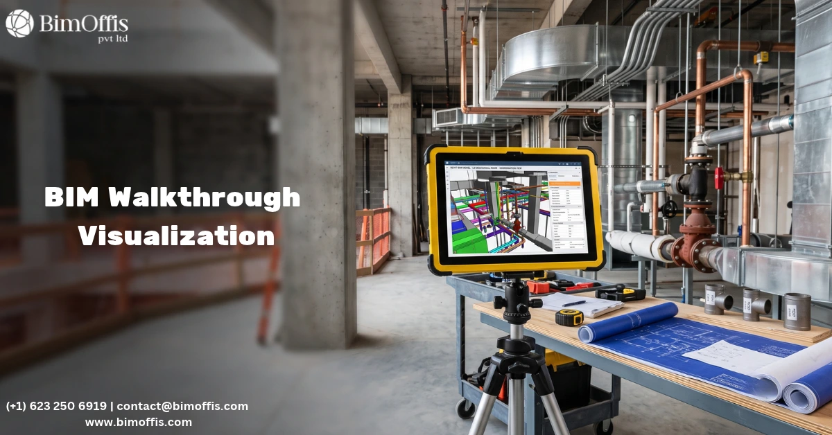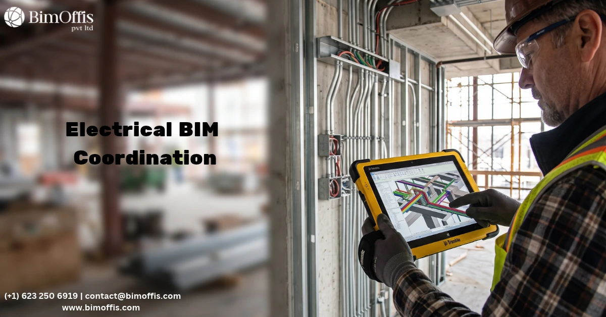
Electrical modeling in BIM is the discipline that takes an electrical design from a 2D schematic exercise into a three-dimensional coordinated process. Teams find spatial conflicts during design instead of on site. Installation planning happens against real coordinated geometry. Documentation comes from a model that actually reflects the current state of the design.
Let me start with something that electrical engineers and MEP coordinators both recognise from direct experience.
The ceiling void on a large commercial floor plate is a genuinely contested space. Every MEP discipline needs routes through it. The mechanical engineer needs height for main ductwork runs and secondary branches. The plumbing engineer needs space for pipework and the fall gradients that gravity drainage requires. The fire protection engineer needs routes for sprinkler mains and branches across every part of the floor. The electrical engineer needs paths for main cable trays, secondary containment, lighting circuits, data infrastructure, and the conduit runs that feed every outlet and fitting in the space.
Each discipline often produces these requirements as 2D drawings in isolation. Coordination through overlay and review then consistently misses the three-dimensional conflicts that only become apparent when every system sits in the same spatial environment simultaneously. Those missed conflicts show up on site as stopped work, rerouted containment, and programme delays. They cost significantly more than the electrical modeling that would have prevented them.
Electrical modeling in BIM solves this problem. It creates the complete electrical system as an accurate three-dimensional model that sits in the same coordinated environment as every other building system before any installation begins.
What Electrical Modeling in BIM Actually Involves
Building the Electrical System as Intelligent 3D Objects
Electrical modeling means creating every element of the electrical system as an accurately dimensioned three-dimensional object in the BIM environment, rather than as a line or symbol on a 2D plan.
Cable tray systems appear in the model at their actual installed dimensions. They are not schematic lines that suggest a route. They are correctly sized tray objects that show the actual width, the actual depth, the actual cover where applicable, and the actual support system that fixes the trays to the structure. Every run, every bend, every tee, and every transition appears at its actual position in the coordinated ceiling void environment.
Conduit systems follow their actual routing paths through walls, ceilings, and floors. Where multiple conduits run together in a bank, the bank appears at its actual combined dimensions, not as a single schematic line. Where conduits penetrate structural or fire-rated elements, the electrical model shows the penetration positions and sizes, so structural and fire protection coordination can happen during design.
Distribution boards, switchboards, and transformer equipment appear at their actual dimensional footprints. The model shows the required clearance zones in front of every panel, the cable entry routes above and below each enclosure, and the maintenance access space around every piece of distribution equipment. This clearance zone modeling lets the coordination process catch the spatial conflicts that would otherwise block safe maintenance access in the installed building.
Luminaires, emergency lights, and exit signs appear at their actual installed positions with their actual mounting configurations. The coordinated model shows the relationship between lighting positions and the reflected ceiling grid, so teams can confirm final positions before any ceiling installation begins.
How Electrical Modeling Improves BIM Design Coordination
Three-Dimensional Clash Detection That Finds Real Conflicts
Electrical modeling delivers one major coordination improvement above all others. It lets teams check the electrical design against every other building system in three dimensions simultaneously, rather than through manual 2D drawing overlay.
The electrical model sits in the federated coordination environment alongside the structural model, the architectural model, the mechanical model, the plumbing model, and the fire protection model. Automated clash detection then checks every electrical element against every other element in the building. A cable tray that clears a structural beam in plan but clips its bottom flange in section appears as a clash. A conduit that routes through a structural element, shown schematically in the 2D drawing but at its actual size in the model, appears as a clash. A distribution board that blocks maintenance access to an adjacent mechanical unit appears as a soft clash that needs resolution before both pieces of equipment get locked into their positions.
Resolving each of these conflicts during design costs only a model update and a coordination conversation. The same conflicts cost programme delay, rework, and variation claims when they surface during construction. On complex building projects, electrical system density makes coordination conflicts numerous rather than occasional. Catching those conflicts during design consistently justifies the electrical modeling investment.
Coordinating Separation Requirements
Electrical systems carry specific separation requirements between different cable categories, and 2D coordination cannot verify these reliably. High voltage and low voltage cables require physical separation to maintain safety standards. Power cables and data cables require separation to prevent electromagnetic interference that affects data transmission quality. Emergency power circuits require separation from general power circuits to protect life safety systems from failures in the general distribution.
The model places electrical cable tray routes for different cable categories at their actual positions. Teams can then measure the separation distances between them and confirm those distances against the specified requirements before any installation begins. Locations where the proposed routing cannot achieve the required separation appear as soft clashes that need routing revision. 2D drawing coordination simply cannot achieve this level of separation coordination with any consistency.
Supporting Riser and Plant Room Coordination
Electrical risers carry significant volumes of cable tray, conduit, and busbar trunking through building cores that also hold mechanical, plumbing, and fire protection risers. Coordinating all of these services within the physical dimensions of the riser shaft requires three-dimensional modeling rather than two-dimensional overlay.
Electrical modeling in BIM places every electrical riser element at its actual installed dimensions in the coordinated riser environment. The coordination checks that identify conflicts between electrical risers and other services happen in the model during design, when modifications are relatively straightforward. They do not happen on site, where the riser shaft becomes a constrained construction zone and modifications require significant disruption and cost.
Plant rooms carry the highest MEP service density of any zone in a building. Main switchrooms, UPS rooms, and generator enclosures all require careful coordination of the electrical equipment, its required clearances, its cable entry and exit routes, and the structural and architectural elements that share the plant room space. Electrical modeling in plant rooms ensures this coordination happens during design, when teams can still adjust the floor plan and the vertical clearances to accommodate all requirements. It should not happen during installation, when the structure is fixed and the equipment has already arrived.
What Electrical Modeling Delivers for Construction and Beyond
Installation Documentation That Reflects the Coordinated Design
Once the electrical system exists as an accurately modeled, coordinated BIM model, the construction documentation that the installation team works from comes directly from the model rather than from a separate manual drawing exercise.
Cable tray layout drawings, showing tray routes, tray sizes, and tray elevations on each floor, derive from the model with dimensions that reflect the current coordinated design. Panel schedules, listing every distribution board with its location, its incoming supply details, and its circuit assignments, derive from the model data. Luminaire schedules, listing every light fitting with its type, its circuit reference, and its emergency status, derive from the model too.
When the coordination process changes a cable tray route, repositions a panel, or modifies a lighting layout, the documentation updates with the model. The installation team therefore always works from documentation that reflects the current coordinated design, rather than drawings that predate the last round of coordination changes.
Prefabrication Reliability
Electrical modeling in BIM makes genuine off-site prefabrication of electrical assemblies reliable in ways that 2D design coordination cannot support consistently.
Once cable tray routes exist as accurately coordinated three-dimensional geometry, teams can prefabricate sections of cable tray off-site to the exact dimensions the model specifies. The prefabricated sections then arrive on site and install in the coordinated positions without field adjustment or modification. Once panel assemblies exist in the model with their actual cable entry configurations, teams can prefabricate the cable management assemblies that organise the cables entering and leaving each panel to the specific configuration the model defines.
This prefabrication reliability depends entirely on the accuracy of the electrical modeling. When the model accurately represents the real installation environment, the prefabricated assemblies fit correctly. When the model contains approximations, the prefabricated assemblies need field modification, and that eliminates the efficiency gain prefabrication was supposed to deliver.
Operational Value After Construction
The electrical model carries value beyond the construction phase. An accurate as-built electrical model gives the facilities management team a queryable record of the installed electrical infrastructure, and that record supports faster fault response, more effective planned maintenance, and more reliable design for future electrical modifications.
Panel locations, circuit layouts, cable routes, and equipment specifications all exist in a model that the facilities team can interrogate directly. When a fault occurs, the team traces the relevant circuit in the model rather than in the building. When a system modification is planned, the design team starts from a verified record of the current installation, rather than from original drawings that may have diverged from reality through years of undocumented modifications.
The Bottom Line
Electrical modeling in BIM delivers better design coordination by putting the electrical design where it belongs throughout the project. It sits in the same three-dimensional environment as every other building system, gets checked systematically for conflicts, stays reliable as a reference for installation planning and prefabrication, and serves as the source from which construction documentation and operational records derive.
The building projects that consistently deliver electrical installations that fit in the available space, install on the planned sequence, commission without coordination surprises, and support effective facilities management throughout the building’s life share one trait. Their teams invested in electrical modeling properly, from early design development through to as-built model delivery.
That is what good electrical modeling delivers. On any building project where electrical system complexity makes coordination failures both likely and expensive, investing in it properly remains one of the most direct and most cost-effective ways to protect the programme, the budget, and the quality of the completed building.
Improve BIM design coordination with professional electrical modeling services that support accurate layouts, clash detection, system planning, and efficient installation.
Frequently Asked Questions from Clients
What is electrical modeling in BIM?
Electrical modeling in BIM creates accurate 3D representations of electrical systems for better design coordination and installation planning.
How does electrical modeling improve BIM coordination?
It helps teams identify electrical clashes with structural, mechanical, plumbing, and fire protection systems before construction.
What electrical elements are included in BIM modeling?
Electrical BIM models can include cable trays, conduits, panels, switchboards, luminaires, equipment, and other electrical components.
How does electrical modeling support clash detection?
It places electrical systems in a shared 3D environment where teams can detect and resolve spatial conflicts before installation.
Can electrical BIM models support prefabrication?
Yes, accurate electrical models provide coordinated dimensions and routes that can support off-site fabrication of electrical assemblies.
What are the benefits of an as-built electrical BIM model?
An as-built electrical model provides a reliable digital record of installed systems for maintenance, fault tracing, and future modifications.