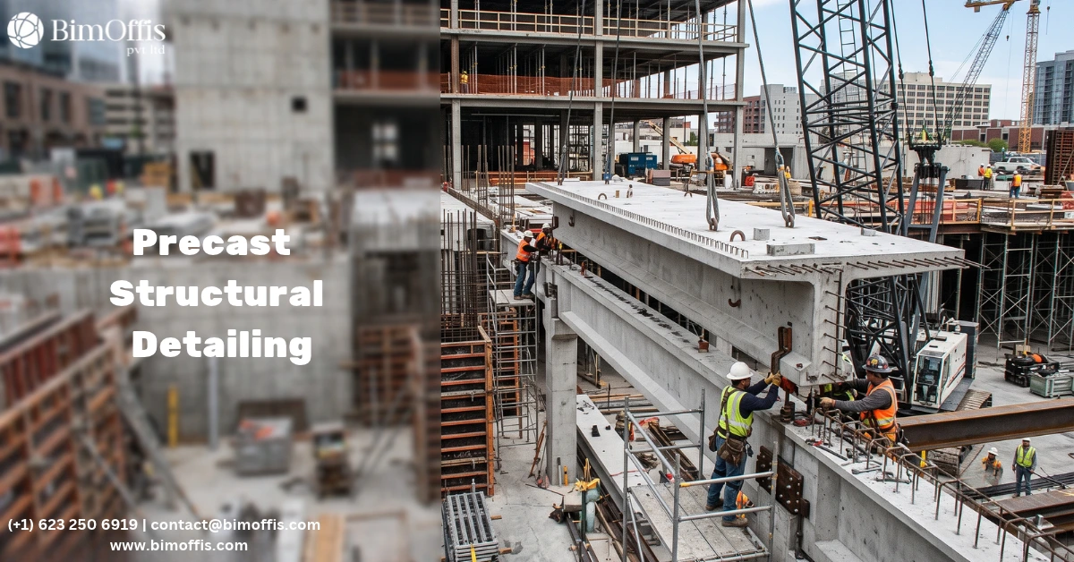
Precast detailing turns a structural engineer’s design into the fabrication drawings, reinforcement details, and erection documents a precast manufacturer needs. These documents let the manufacturer produce and install elements correctly and efficiently.
Structural engineers, precast manufacturers, and site managers all recognise this from project experience.
Why Project Teams Choose Precast Construction
Teams choose precast concrete for specific reasons: faster erection, better finish quality, and more consistent structural performance. A controlled factory environment produces elements to tighter tolerances than site-cast concrete usually achieves. These are real advantages, and they justify the investment in precast over other structural solutions.
Every one of these advantages depends on correct detailing before production starts. Poor fit-up stalls erection and cancels out the speed advantage. Incorrect embedded item positions force rework and cancel out the quality advantage. Detailing that isn’t precise enough lets reinforcement layouts vary between production batches, cancelling out the consistency advantage.
Precast detailing protects these advantages, carrying design intent through to the finished structure. Done well, elements leave the production line correctly dimensioned and reinforced, with embedded items positioned accurately, ready for erection in the planned sequence. Done poorly, precast construction becomes the most troublesome part of the project instead of one of its biggest strengths.
What Precast Detailing Covers
The Complete Documentation Set for Precast Fabrication
Precast detailing produces several categories of documentation that define every aspect of a precast element, from geometry through to installation.
General arrangement drawings show the complete precast structure layout. Every element carries a unique mark number, sits at its correct location, and aligns correctly with adjacent elements and the building’s primary structural grid. These drawings give the production planning team a full picture of the package, and give the erection team the layout reference they need to place each element correctly.
Individual element drawings cover every distinct precast element. Each one shows the exact external geometry, including openings, recesses, projections, and chamfers. The reinforcement layout appears in full, with bar marks, sizes, spacings, cover dimensions, and special reinforcement at connections, openings, and lifting points.
Embedded item drawings show where every cast-in item sits and how it’s specified. Lifting anchors, connection plates, anchor boxes, MEP sleeves, and conduit runs all need exact positions before they go into the mould. Getting these positions right matters enormously: a misplaced lifting anchor creates a safety issue, and a misplaced connection plate creates an erection problem that only rework or replacement can fix.
Connection details cover every connection configuration in the structure column to foundation, beam to column, panel to frame, wall panel to floor slab. Each detail specifies the components involved, their dimensions, the tolerances the connection must accommodate, and the grouting or bolting sequence needed to complete it.
Reinforcement schedules list every bar in every element, with mark number, size, shape code, bend dimensions, and quantity. Accurate schedules let teams assemble each reinforcement cage from the scheduled bars without modification. Inaccurate ones force field bending or bar replacement, adding cost and time.
Why Precast Detailing Quality Matters
The Production Consequences of Poor Detailing
Precast manufacturing runs as continuous production. A problem with one element can stop the line and affect delivery for the whole package.
An unclear detail drawing leads to a mould set up incorrectly, delaying that pour and possibly the pours that follow. Incorrect bar dimensions produce a reinforcement cage that doesn’t fit the mould, so the team needs to modify or replace it before the pour can proceed. An unclear embedded item position can put that item in the wrong place, creating an element that may need rework after demoulding.
Each of these problems adds time and cost to the element. Across a package with hundreds of elements and a tight programme, these detailing-driven problems add up fast.
The precast manufacturer’s relationship with the main contractor depends on hitting the programme. Detailing problems that cause production delays ripple into the contractor’s erection schedule, and every trade that follows precast erection feels the delay too. The real cost of a detailing error isn’t just production cost, it’s the downstream impact on every activity waiting on precast completion.
The Erection Consequences of Incorrect Detailing
Precast erection is high-cost and safety-critical. The crane and erection team cost significant money every day, and the structure needs careful management for stability before the permanent structure is fully in place.
Correctly detailed elements let erection proceed smoothly: the crane lifts, the team guides the element into position, connections engage, and the crane moves to the next lift. The programme advances as planned.
Detailing errors stop erection at the point where the problem surfaces. A connection plate in the wrong position stops a connection from engaging. An incorrect bearing dimension stops an element from bearing correctly on its neighbour. The crane and erection team wait while someone assesses the problem and finds a fix and every hour of standing time carries a cost that correct detailing would have avoided.
How Good Precast Detailing Works in Practice
Coordinating With the Structural Design
Good precast detailing starts with a thorough understanding of the structural engineer’s design intent. Detailers need to grasp not just each element’s geometry but the structural logic behind the design: load paths, connection behaviour requirements, and the tolerances the structural design assumes.
This understanding lets the detailer make sound judgment calls on decisions the structural drawings leave implicit positioning reinforcement relative to the neutral axis, specifying cover for the relevant exposure conditions, and detailing reinforcement at connections to achieve the intended structural behaviour. These judgments call for structural understanding, not just drafting skill.
Good precast detailing also keeps communication open with the structural engineer throughout the process. When the detailer’s interpretation needs confirming, the question gets raised and resolved before the drawing is issued, not after the element goes into production.
Coordinating With the Production Process
Good precast detailing also requires understanding the manufacturer’s production process: mould systems, cage assembly sequence, embedded item installation, demoulding, handling equipment, and finishing and repair procedures.
Understanding this process lets the detailer produce drawings that work with production rather than against it, reinforcement cages that assemble efficiently, embedded items positioned for easy access during the pour, and element geometries that demould cleanly without complex mould configurations that add cost and risk.
This awareness is what separates detailing that streamlines fabrication from detailing that’s technically correct but inefficient in production.
Checking and Coordination
Good precast detailing includes systematic checking before drawings go out. Dimensional checks confirm element dimensions match the structural grid and adjacent element interfaces. Reinforcement checks confirm bar sizes, spacings, and cover match the structural design requirements. Embedded item checks confirm every item sits in the right position with the right specification.
Coordination checks confirm the detailed elements work with every other building system they interface with MEP sleeves in the positions the MEP engineer needs, connection positions consistent between precast drawings and adjacent structural elements, and architectural finish requirements consistent with the production process that will achieve them.
How BIM Improves Precast Detailing
Three-Dimensional Coordination Before Production
BIM-based precast detailing places every element in a 3D model that coordinates against the architectural, structural, and MEP models before production starts. Conflicts that would once have surfaced during erection now surface during coordination, where teams can resolve them early.
A repositioned MEP sleeve avoids a clash with the main reinforcement cage before the mould is prepared. A relocated connection plate avoids a clash with a beam from the adjacent structural system before the cage is assembled. These fixes cost modeling time, not production cost or erection delay.
Automated Production Documentation
When precast elements exist as accurately modeled objects in BIM, teams can generate element drawings, reinforcement schedules, and erection drawings straight from the model instead of producing them manually. This approach keeps drawings and schedules dimensionally consistent with each other and the overall structural model.
When designs change, the model updates, and production documentation follows from the updated model. The manufacturer always works from current documentation, not a superseded version from earlier in the design process.
The Bottom Line
Precast detailing for streamlined fabrication preserves the speed, quality, and consistency advantages of precast concrete construction, from design intent through to the installed structure.
Good detailing gives the manufacturer documentation they can trust, gives the site team erection documentation they can follow efficiently, and gives everyone a coordination record confirming that each element fits its neighbours and every building system it touches.
The precast structures that deliver their promised efficiency are the ones where the detailing was thorough, the coordination was complete, and the documentation was accurate. That’s what good precast detailing makes possible.
Streamline structural fabrication with professional precast detailing services that support clear drawings, precise reinforcement details, and efficient installation.
Frequently Asked Questions from Clients
What is precast detailing?
Precast detailing converts structural designs into fabrication drawings, reinforcement details, and erection documents.
What does precast detailing include?
It includes element drawings, reinforcement schedules, embedded item details, connection details, and general arrangement drawings.
Why is accurate precast detailing important?
Accurate detailing helps prevent production errors, rework, erection delays, and unnecessary project costs.
How does BIM improve precast detailing?
BIM enables 3D coordination to identify conflicts before production and helps maintain consistent production documentation.
What are reinforcement schedules in precast detailing?
Reinforcement schedules list bar marks, sizes, shapes, bend dimensions, and quantities for each precast element.
How does precast detailing support efficient fabrication?
It provides coordinated drawings that help manufacturers produce, assemble, and install precast elements correctly and efficiently.