Anyone who has worked on a construction site or in a manufacturing shop has probably heard this term thrown around without much explanation. Fabrication drawings sound technical, and they are. But understanding what they do and why they matter isn’t complicated once someone breaks it down properly. So let’s do that.
The Basic Idea
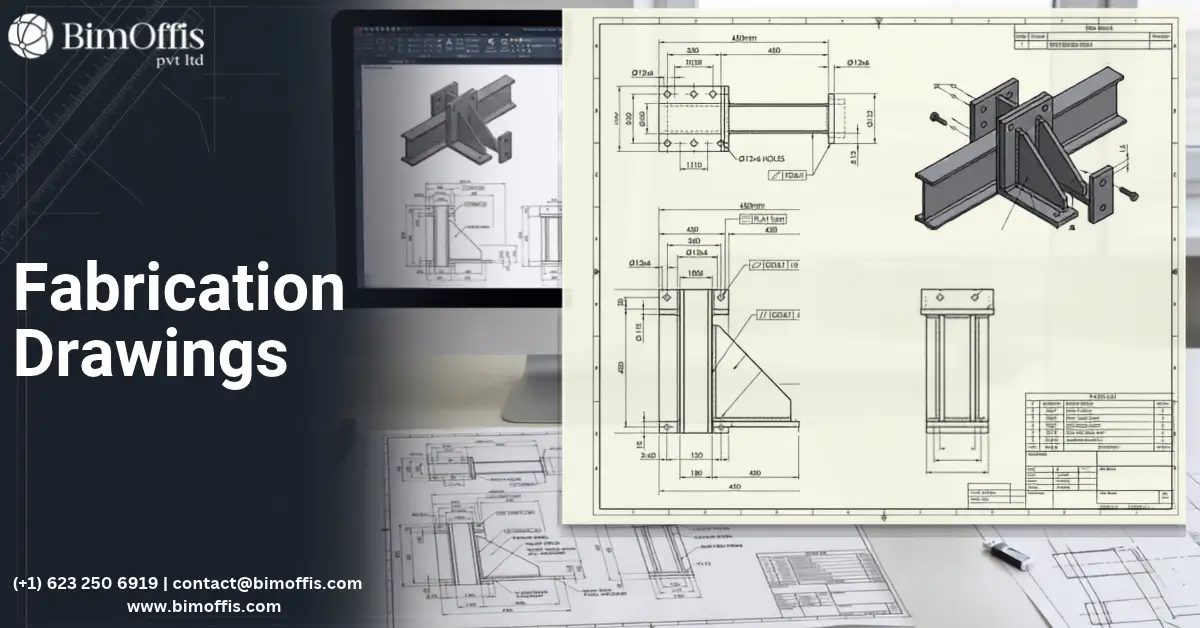
Fabrication drawings are detailed technical drawings that tell a shop or manufacturer exactly how to build a specific component. These sheets skip the finished-building look and the rough sizing. Instead, they specify exact dimensions, exact materials, exact connections, and exact tolerances. A welder, fabricator, or machine operator picks up these drawings and follows them step by step to produce the actual physical piece.
Think about it this way. An architectural drawing shows a steel beam as a line in a floor plan. It tells you where the beam goes and roughly what it does structurally. But it doesn’t tell the fabricator which bolt holes to drill, where the welds go, what gauge the plate is, or how the connection plate attaches to the column. A fabrication drawing provides that level of detail. Without it, nobody in a shop could build the thing correctly.
Who Actually Uses Them
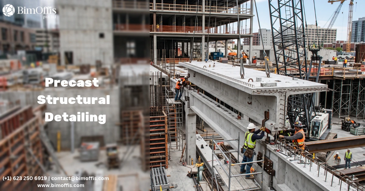
Structural steel work relies on fabrication drawings constantly, but they’re not limited to that field. Sheet metal shops use them. Millwork and casework manufacturers use them. Precast concrete producers use them. HVAC ductwork fabricators use them too. Basically, anywhere a physical component gets built off-site and travels to a project, someone needed a fabrication drawing to make that happen.
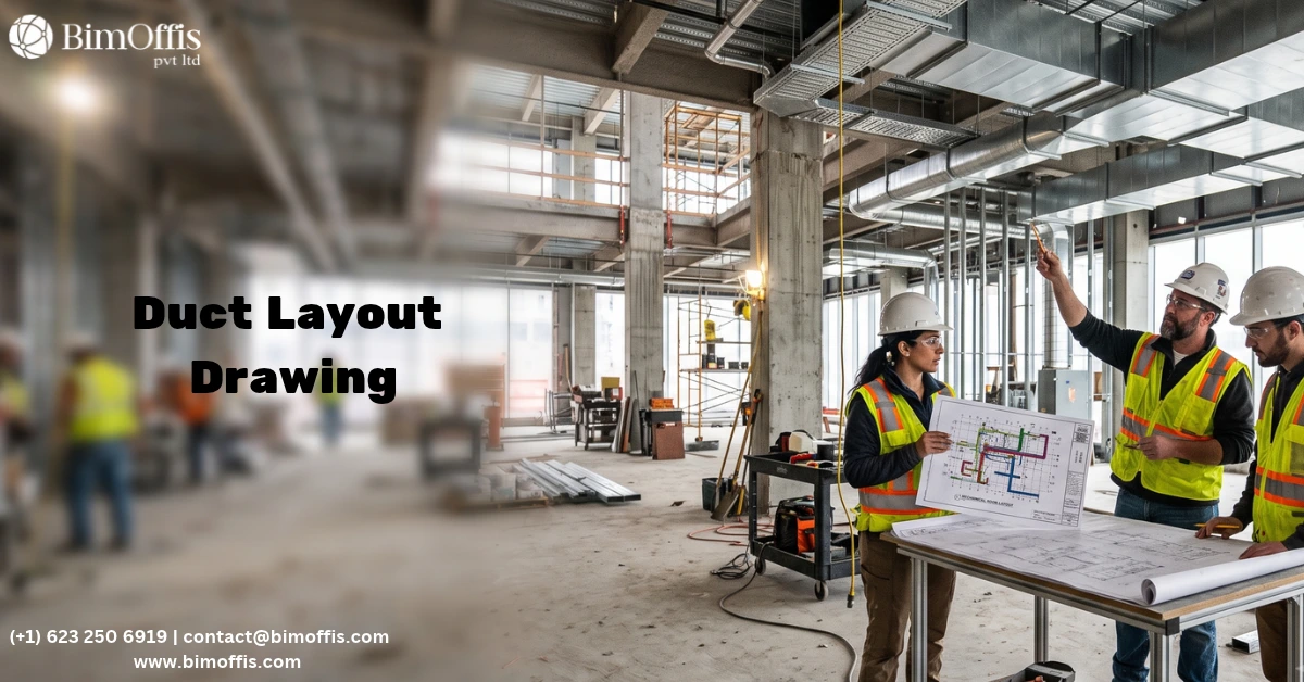
Detailers create these drawings, not the original architect or engineer. A structural engineer designs a connection and specifies the loads it needs to carry. A steel detailer then takes that design intent and works out every physical detail required to manufacture and install it. That detailer’s drawing becomes the instruction manual the fabrication shop follows.
What’s Actually On a Fabrication Drawing
A good fabrication drawing packs in dense information, and that density is the whole point. You’ll typically find exact dimensions down to fractions of an inch or millimeters, depending on the region. Material specifications, including grade and thickness, show up too. Weld symbols indicate the type, size, and location of every weld. Bolt patterns call out hole sizes and spacing precisely. Finish requirements cover things like galvanizing or paint coating.
Beyond the geometry, the drawing usually includes a bill of materials listing every piece needed for that component. Piece marks let the shop and site crew track individual parts through fabrication and erection. Some drawings also show assembly sequences that outline the order for putting pieces together. On complex connections, you might also see camber requirements, tolerances, and notes referencing project specifications or applicable codes.
None of this counts as decorative detail. A fabricator needs every dimension and symbol on that sheet to produce the part correctly. A missing or wrong piece of information can mean a part that doesn’t fit once it shows up on site.
How They Differ From Shop Drawings and Construction Drawings
People mix these terms up a lot, so it’s worth clarifying. Construction drawings, sometimes called design drawings, come from the architect and engineer. They describe design intent for the whole project. Shop drawings sit somewhere in between. A contractor or supplier prepares them to show how the design will actually get built, and the design team often reviews them before fabrication starts.
Fabrication drawings typically form the most detailed layer, and shops produce them once shop drawings gain approval. These sheets focus purely on giving the shop floor everything it needs to cut, weld, drill, and assemble the actual pieces. In practice, especially in structural steel, people sometimes use the terms “shop drawing” and “fabrication drawing” interchangeably. Technically, though, the fabrication drawing carries the full manufacturing detail.
Why They Matter So Much
Get a fabrication drawing wrong, or skip the process and work straight off design drawings, and the consequences show up fast. Pieces arrive on site that don’t fit. Bolt holes don’t line up. Connections built to carry specific loads end up underbuilt or overbuilt. Rework on a fabricated steel piece isn’t like fixing a mistake on paper. It means cutting metal, re-welding, and sometimes scrapping an entire piece and starting over. That costs real time and real money on a project schedule that usually can’t absorb the delay.
Good fabrication drawings protect everyone involved. The fabricator gets a clear, approved reference to build from, which limits disputes about responsibility when something doesn’t match. The general contractor gets components that actually fit together on site instead of surprises during erection. And the owner ends up with a building that engineers actually built the way they designed it, not an approximation of it.
Where 3D Modeling Fits Into This
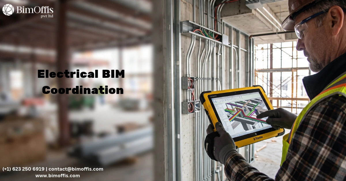
Modern fabrication drawing workflows increasingly pull from 3D models instead of starting from scratch in 2D. When a detailer builds the connection in a 3D environment, the software can generate fabrication drawings directly from that model. This process cuts down on errors that creep in when someone manually redraws geometry across multiple sheets. It’s part of a broader industry shift, one that mirrors the same conversation happening between CAD and BIM more generally, where detail and data increasingly live in a coordinated model rather than scattered across disconnected drawings.
Fabrication drawings will keep bridging the gap between design intent and a physical, buildable part, no matter how the tools producing them keep evolving.
Ensure precise fabrication with professional shop drawing services that help reduce errors and keep your construction workflow on track.
Frequently Asked Questions from Clients
What are fabrication drawings?
Fabrication drawings provide detailed instructions for manufacturing and assembling specific construction components.
Who prepares fabrication drawings?
Fabrication drawings are typically prepared by skilled detailers based on approved design and engineering information.
What information do fabrication drawings include?
They include dimensions, materials, welds, bolt locations, tolerances, finishes, and assembly details.
What is the difference between fabrication and construction drawings?
Construction drawings show overall design intent, while fabrication drawings provide detailed manufacturing instructions.
Why are fabrication drawings important?
They help reduce fabrication errors, improve accuracy, and ensure components fit correctly during installation.
How does 3D modeling improve fabrication drawings?
3D modeling helps generate accurate fabrication drawings while reducing manual errors and improving coordination.