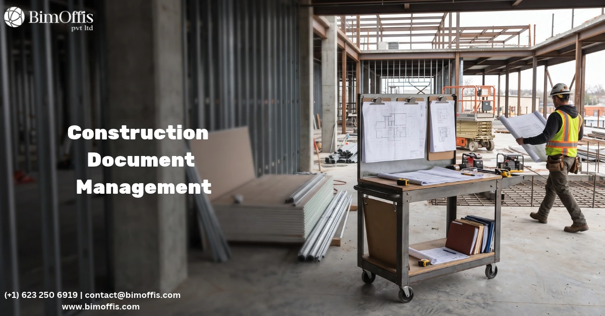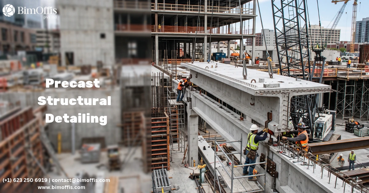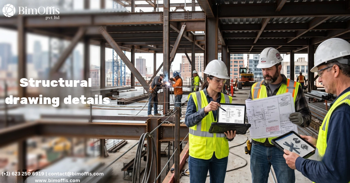
Structural shop drawings turn a structural engineer’s design into fabrication instructions. A steel fabricator, a precast manufacturer, or a timber framer uses these instructions to produce structural elements correctly.
Let’s start with something that structural engineers, contractors, and fabricators all know from experience.
A significant gap separates a structural engineer’s design drawings from a fabricator’s shop floor. Design drawings show the structural intent. They show member sizes, connection types, load cases, and the overall structural system. They don’t show the exact geometry of every connection. They don’t show the specific weld sizes for each joint, the precise hole patterns for bolted connections, the exact cut lengths for every member, or the fabrication sequence for complex assemblies.
Structural shop drawings fill that gap. Correct shop drawings ensure fabricated elements arrive on site with the right dimensions, the right connections, and the right geometry to install correctly. Poor shop drawings cause problems that surface during installation. Fixing those problems on site costs far more than getting the drawings right in the first place.
What Structural Shop Drawings Cover
The Full Scope of Structural Shop Drawing Documentation
Structural shop drawings cover every aspect of a structural element. They run from the raw material specification through to the final installed configuration. Take a steel-framed building as an example. A complete set of structural shop drawings includes several distinct document types, and together they define every element of the structural steel package.
General arrangement drawings show the overall layout of the structural steel frame. Every member carries a unique mark number. Each one sits at its correct location and holds the correct orientation relative to adjacent members. These drawings give the fabrication shop and the erection team a complete picture of the steel package they’re producing and installing.
Individual member drawings cover every distinct steel section in the project. For each member, the shop drawing shows the exact length, the cross-sectional profile and grade, and the end preparation each connection requires. It also shows the positions of any holes, slots, or weld preparations, plus any cleats, plates, or other attached components.
Connection details show the specific configuration of every structural connection in the frame. They cover how the beam connects to the column, how the secondary beam frames into the primary beam, and how the column base connects to the foundation. Each connection detail lists the required components, their exact dimensions, the weld sizes or bolt specifications, and the assembly sequence.
Erection drawings show the sequence and method for installing the structural steel. They indicate which members go in first to create a stable structure. They also specify the temporary bracing the erection needs, plus the crane configurations and lift points each member requires. Good erection drawings protect the structural integrity of the building during construction. They also protect the safety of the erection team.
Material and Fabrication Specifications
Structural shop drawings carry explicit material specifications for every element. Steel grade, section size, surface finish, and paint specification all need clear documentation. So do specialist treatments such as galvanising or intumescent fire protection. Clear specifications let the fabrication shop order the correct material and apply the correct surface treatments before the steel leaves the workshop.
Weld specifications define the type, size, and quality of every weld in the assembly. For structural welds, these specifications reference the relevant welding standards. They also define the inspection requirements for each weld category.
Why Structural Shop Drawing Quality Matters
The Cost of Getting It Wrong
Structural fabrication is expensive and largely irreversible. A shop cuts a steel member to length, drills it with a specific hole pattern, and fits it with connection components. If the shop drawing behind that work turns out wrong, fixing the member becomes difficult and costly.
Consider a column that arrives on site 50mm shorter than the foundation baseplate requires. That calls for a significant modification or a full replacement. Or consider a beam end with an eight-bolt connection detail when the design specifies a twelve-bolt pattern. That beam needs modification before installation. Both situations cost more to resolve on site than they would have cost to fix during shop drawing production.
The programme impact of fabrication errors compounds quickly on structural steelwork projects. Structural steel typically sits on the critical path. If incorrectly fabricated elements can’t go in, every trade that depends on the structure gets delayed too. The cost of that programme delay can significantly exceed the direct cost of the fabrication error itself.
The Coordination Function of Shop Drawing Review
Structural shop drawings serve a coordination function as well as a fabrication function. The structural engineer reviews submitted shop drawings as a checkpoint. This review confirms the fabricator’s interpretation of the design before any steel gets cut.
This step catches discrepancies between the design intent and the fabricator’s proposed approach early, while the team can still resolve them at a desk. Say a fabricator simplifies a connection configuration in a way that doesn’t meet the engineer’s requirements. The review flags that issue instead of an installation inspection catching it later. Similarly, if a member’s size differs slightly from the specification, the review corrects it before fabrication.
The review process also catches coordination issues between structural shop drawings and other building systems. Say an MEP penetration through a structural member never appeared on the structural design drawings. That conflict surfaces during shop drawing review, and the fabricator raises it as a request for information. The team then designs the penetration correctly and builds it into the fabricated member, instead of field-drilling it on site without engineering approval.
The Structural Shop Drawing Process
From Design to Submission
The process begins when the structural engineer issues design drawings and specifications to the fabricator. These documents form the basis for shop drawing production. The fabricator’s detailing team then works through every element of the structural system. They produce shop drawings that show exactly how they propose to fabricate each one.
This stage requires the detailing team to resolve every fabrication question the design drawings leave open. They must set the exact cut length of each member, accounting for connection clearances and fabrication tolerances. They must define the specific weld preparation at each end of each member. They must also work out the hole patterns for bolted connections, accounting for bolt diameters, edge distances, and minimum spacing requirements, plus the assembly sequence for complex built-up sections.
A well-resourced, experienced detailing team resolves these questions correctly. Their drawings let the structural engineer review efficiently and let the fabricator work with confidence. An inexperienced or under-resourced team produces drawings with gaps, errors, and assumptions instead. Those drawings need extensive revision before they become fit for fabrication.
The Review and Approval Process
Once the fabricator submits the shop drawings, the structural engineer reviews them against the design drawings and specifications. This review confirms three things: the fabricator interpreted the structural design correctly, all connection details meet the structural requirements, and all material specifications match the design.
The review uses a formal marking system. Correct drawings get an approved for fabrication mark. Drawings with minor comments that don’t affect fabrication get approved too, with the comments noted but no resubmission required. Drawings with significant discrepancies go back to the fabricator, along with comments for revision and resubmission, before fabrication can start.
This process also checks that the structural shop drawings coordinate with the architectural and MEP drawings for the project. Structural elements need to sit at the positions and elevations the architectural drawings require. Structural penetrations need to sit where the MEP drawings require them. Catching these misalignments during review, rather than on site, prevents expensive coordination failures later.
How BIM Improves Structural Shop Drawing Production
Three-Dimensional Coordination Before Fabrication
BIM-based structural shop drawing production places the structural model in a three-dimensional coordinated environment alongside the architectural and MEP models. This coordination happens before shop drawing production starts, not after.
Say a structural member would have conflicted with a main duct run. The team repositions it in the model before anyone produces the shop drawing. Likewise, if a column base plate would have required a penetration through a below-slab service, the team redesigns it in the model before the fabricator commits to a specific plate configuration. These fixes cost modeling time rather than fabrication cost. That’s the fundamental financial benefit of BIM-based structural coordination.
Drawing Production From the Model
Structural elements exist as accurately modeled objects in a BIM environment. That means teams can generate shop drawings straight from the model instead of producing them manually as a separate exercise. The cut lengths come from the model geometry. The connection configurations come from the modeled connections. The hole patterns come from the modeled fastener positions.
This model-derived production keeps the shop drawings consistent with the coordinated model. When the coordination process changes a structural element, the shop drawing updates automatically to reflect that change, because it derives from the updated model. The fabricator always works from drawings that reflect the current coordinated design, never a pre-coordination version that a later update may have superseded.
The Bottom Line
Structural shop drawings matter because they determine whether fabricated elements fit the building correctly. They determine whether connections work as the engineer intended. And they determine whether installation happens without the expensive surprises that incorrect fabrication consistently produces.
The most successful projects deliver structural steel, precast concrete, and timber structures on programme and installed correctly. On these projects, the team produced the structural shop drawings thoroughly, reviewed them rigorously, and coordinated them carefully against the other building systems before any fabrication started.
That’s what good structural shop drawings make possible. On any project where the structural frame is a significant cost and programme item, getting the shop drawing process right protects both.
Improve construction accuracy with professional structural shop drawing services that support precise fabrication, coordination, and efficient on-site installation.
Frequently Asked Questions from Clients
What are structural shop drawings?
Structural shop drawings provide detailed fabrication and installation instructions for structural elements.
What do structural shop drawings include?
They include general arrangement drawings, member details, connection details, erection drawings, and material specifications.
Why are structural shop drawings important?
They help ensure structural elements are fabricated with the correct dimensions, connections, and geometry for proper installation.
Who reviews structural shop drawings?
Structural engineers review shop drawings to verify design interpretation, connections, and material specifications.
How does BIM improve structural shop drawings?
BIM enables 3D coordination before fabrication and allows drawings to be generated directly from the coordinated model.
How do structural shop drawings reduce construction errors?
They identify fabrication and coordination issues before production, helping prevent costly site modifications and delays.