A plumbing plan is one of those documents that every building project needs and very few teams give enough attention to until something goes wrong during installation. Then suddenly everyone wants to know what the plumbing plan shows and why the information does not match what the installer is finding on site.
Getting a plumbing plan right before installation starts is significantly cheaper than getting it wrong. Let me explain what a good plumbing plan involves, what it needs to show, and how to create one that actually serves the project.
What a Plumbing Plan Actually Is
More Than Just Pipe Routes on a Drawing
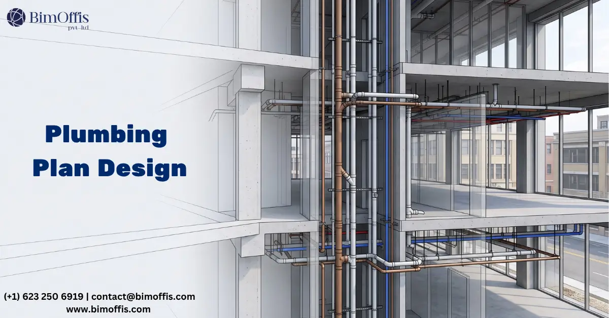
A plumbing plan is a technical document showing the complete water supply, drainage, and waste systems for a building. It communicates where every pipe runs, what size it is, what material it consists of, where every fixture connects, and how the complete system drains and vents.
A basic plumbing plan shows pipe routes and fixture locations. A good plumbing plan shows all of this plus pipe sizes, invert levels, fall gradients, connection details, and isolation valve positions. It also shows coordination between the plumbing system and other building services sharing the same ceiling voids, wall chases, and riser shafts.
The difference between basic and good matters enormously when the plumber arrives on site. A basic plan leaves too many questions unanswered. Consequently, the plumber makes field decisions that may not match the design intent. A good plan answers those questions in advance and gives the installer clear, unambiguous instructions to work from.
The Information a Plumbing Plan Must Cover
Water Supply Systems
The water supply section covers the complete cold and hot water distribution systems. It runs from the incoming mains supply to every outlet in the building.
Cold water supply drawings show the incoming mains connection point, the water meter, and main isolation valve positions. In addition, these drawings cover the cold water storage tank, booster pump arrangement if required, and distribution pipework routes to every cold water outlet.
Hot water supply drawings show the hot water generation equipment, the primary and secondary circulation systems, and the distribution routes to every hot water outlet. On larger buildings, moreover, the hot water system needs to show the circulation return pipework. This prevents the dead leg lengths that cause temperature problems and Legionella risk.
Furthermore, the water supply drawings need to show pipe sizes at every section of the system. Undersized pipes produce flow rates and pressures that do not meet fixture requirements. Oversized pipes waste material and space. Consequently, pipe sizes on a good plumbing plan reflect proper hydraulic calculations rather than rule of thumb estimates.
Drainage and Waste Systems
The drainage section is often the most technically demanding part of a plumbing plan. Gravity drainage systems need to maintain correct fall gradients throughout their length. Drainage cannot run uphill. It cannot run at too shallow a gradient because solids will not carry. It cannot run at too steep a gradient because liquid runs ahead of solids and leaves them behind.
Drainage drawings show every sanitary fixture and branch connections from fixtures to stack pipes. Additionally, these drawings cover stack pipe routes from fixture connections to the underground drainage system, along with the underground drainage network from the stacks to the sewer connection or treatment system.
Critically, drainage drawings need to show invert levels at every significant point. The invert level is the bottom of the internal pipe bore at that point. Showing invert levels allows the plumber and site team to verify adequate fall throughout the system and that connections work at the correct levels.
Vent Systems
Plumbing vent systems are one of the most frequently underdesigned elements in plumbing plans for smaller building projects. Every drainage system needs ventilation. Without it, trap seals siphon and sewer gases enter the building.
The vent system drawings show the primary ventilation stacks that carry from the drainage system up through the roof. Additionally, the drawings cover branch ventilation pipes protecting individual fixture traps and anti-siphon valves that teams deploy where conventional venting is not practical.
How to Create a Plumbing Plan Step by Step
Start With the Fixture Schedule
Before drawing a single pipe, establish exactly what fixtures and equipment the plumbing system needs to serve. Every fixture in the building needs to appear in a fixture schedule. The schedule should include cold water demand, hot water demand, drainage connection size, and trap requirements.
This fixture schedule is the foundation the plumbing plan builds on. It tells you the total water demand the supply system needs to carry. Moreover, it tells you the drainage flow rates the drainage system needs to handle and the number and types of trap seals the ventilation system needs to protect.
Furthermore, the fixture schedule coordinates the plumbing plan with the architectural drawings. If the schedule lists a fixture in a location that architectural drawings show differently, resolve the discrepancy before the plumbing design proceeds rather than during installation.
Set Out the Drainage System First
The most important sequencing decision in creating a plumbing plan is to design the drainage system before the water supply system. Drainage is the least flexible part of the plumbing design. It needs specific fall gradients. It needs to connect to the underground drainage system at specific invert levels. It needs routing paths that maintain those gradients throughout.
Water supply pipework has much more flexibility. It can run horizontally, vertically, or at any angle. It can also be rerouted relatively easily if it conflicts with another building system. Drainage, however, cannot.
Start by establishing the position of the main drainage stacks. These sit typically in or adjacent to the building’s wet areas and core zones. Then design the underground drainage network, establishing invert levels at the connection points to the sewer. Consequently, work back up through the system from these established levels, confirming adequate fall throughout every branch and stack.
Route the Supply Pipework
With the drainage system established, design the water supply pipework routes around it. The incoming mains connection point is typically determined by the location of the public sewer and water main. Start with this fixed point and work through the distribution system from the supply source to the furthest outlet.
Mark the positions of the main isolation valves, the water meters, any pressure reducing valves, and the cold water storage or pressurisation equipment. Then route the main distribution pipes from these elements through the building to serve each floor and each wet area. Branch pipework routes from the mains to individual fixtures follow once the main distribution layout is established.
Additionally, coordinate the plumbing supply routes with structural elements, ceiling voids, and other MEP services during this stage. A supply pipe route that conflicts with structural grid or HVAC ductwork creates coordination problems. These are cheaper to resolve during design than during installation.
Calculate and Show Pipe Sizes
Once pipe routes are established, sizing calculations determine the correct pipe diameter for every section of the system. Water supply pipe sizing uses demand unit methods or simultaneous flow calculations. These determine the peak flow rate each pipe section needs to carry and select the diameter that delivers that flow at adequate pressure.
Drainage pipe sizing determines the minimum pipe diameter for each section. This is based on the total discharge unit loading and the fall gradient available. Consequently, every pipe size needs to appear clearly on the plumbing plan drawings. The plumber needs to know exactly what pipe diameter to install at every section of the system.
Show Invert Levels and Fall Gradients
Every drainage pipe section on the plumbing plan needs to show the invert level at its high end and the invert level at its low end. It also needs to show the length of the pipe section and the resulting fall gradient.
This information allows verification that the drainage system has adequate and consistent fall throughout its length. Moreover, it allows the site team to check the installation against the design during construction.
Furthermore, where drainage passes through structural elements or needs to achieve specific invert levels, the plumbing plan needs to show these constraints clearly. The structural engineer can then confirm that the required penetrations and levels are achievable.
Common Mistakes in Plumbing Plans
Insufficient Coordination With Other Services
The most common and most expensive mistake in plumbing plan production is failing to coordinate the plumbing system with other MEP services and structural elements sharing the same spaces.
A drainage pipe that needs a specific fall gradient has very limited routing flexibility. If that route conflicts with a structural beam, either the beam needs a structural penetration or the drainage route needs significant change. Consequently, discovering this conflict during installation costs far more than resolving it during design.
Missing Invert Level Information
Plumbing plans that show drainage pipe routes without invert level information leave the plumber to make level decisions on site. Those decisions are sometimes correct and sometimes not. When they are not, moreover, the drainage system either fails to drain properly or cannot connect to the underground drainage system at the correct levels. Significant modification follows as a result.
The Bottom Line
A good plumbing plan covers the complete water supply, drainage, waste, and vent systems for a building. It provides enough detail that the plumber can install the system correctly without making significant field decisions that the design should have addressed.
Creating one properly requires establishing the fixture schedule before designing the systems. Furthermore, design the drainage before the supply. Coordinate plumbing routes with all other building systems. Calculate and show pipe sizes for every section. Additionally, show invert levels for every drainage section.
That level of thoroughness is therefore what produces a plumbing installation that works correctly from the first day of commissioning rather than one that requires investigation, modification, and rework to achieve the performance the building needs.
Create accurate plumbing layouts with professional plumbing BIM and drafting services for better coordination and efficient construction.
Frequently Asked Questions from Clients
What is a plumbing plan?
A plumbing plan shows the water supply, drainage, waste, vent systems, pipe routes, sizes, and fixture connections.
What information should a plumbing plan include?
It should include pipe sizes, fixture locations, invert levels, fall gradients, connection details, and isolation valve positions.
Why should drainage be designed before water supply?
Drainage requires specific fall gradients and fixed connection levels, making it less flexible than water supply pipework.
How are pipe sizes determined in a plumbing plan?
Pipe sizes are determined through water demand and drainage flow calculations to ensure proper system performance.
Why are invert levels important in plumbing drawings?
Invert levels help verify drainage falls and ensure pipes connect correctly at the required levels.
Why is MEP coordination important in plumbing plans?
Coordination prevents plumbing routes from conflicting with structural elements, HVAC systems, and other MEP services.