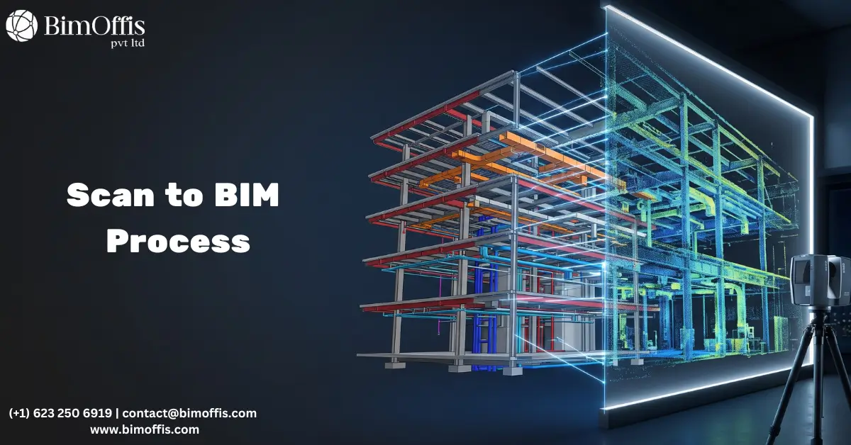
Most people have a general idea of the scan to BIM process. Very few understand it at a level of detail that helps them evaluate whether a provider is doing it properly.
The general idea is simple. First, you scan an existing building with a laser scanner. Next, you turn the scan data into a BIM model. Finally, you use the model for design, renovation, or facilities management.
In practice, though, the reality is more involved. Each stage involves specific decisions, quality checks, and expertise, and these determine whether the final model is genuinely accurate and useful, or merely visually convincing. As a result, understanding what happens between the scanner and the finished BIM model separates teams that get real value from scan to BIM from teams that spend significant money on a model they cannot fully trust.
This article walks through every stage of the process and explains why each one matters.
Stage One: Project Scoping and Survey Planning
Before Anyone Picks Up a Scanner
The scan to BIM process does not start with scanning. It starts with a conversation about what the resulting model needs to do.
This sounds obvious, yet it is the stage that gets rushed most often, and rushing it causes the most problems downstream. For instance, a model built for space planning has different requirements from one built for MEP retrofit coordination. Similarly, a model supporting structural assessment needs different LOD decisions than one supporting architectural renovation documentation.
Why Scope Drives Everything Else
The scope of the scanning programme depends entirely on what the model needs to show. In particular, this includes which areas to cover, at what resolution, and from how many positions. Because of this, good practice defines the model scope clearly before any scanning work begins.
Overall, three questions matter most here. First, what elements need modeling, and at what LOD? Second, which workflows will the model support? Finally, which areas of the building fall within scope, and which do not? In the end, answering these questions early shapes everything that follows.
Stage Two: Laser Scanning on Site
How the Scanner Captures the Building
Once the team defines the scope, they go to site. There, a laser scanner sits in a space and fires laser pulses in every direction from a fixed position. Each pulse then travels outward, hits a surface, and returns. In this way, the scanner measures the travel time of each pulse to calculate the precise distance to that surface.
As a result, the device captures millions of data points from a single position. Each point, in turn, records a precise three-dimensional location. Together, the points captured from one scanner position form what’s called a scan.
Coverage and Overlap
To begin, technicians set the scanner up at multiple positions throughout the building. Then they move it systematically to ensure complete coverage of every area within scope. This matters because the registration stage later needs that shared, overlapping data to combine the scans accurately.
In addition, the scanner captures photographs alongside the geometric data at each position. As a result, these photographs add colour information to the point cloud and make it far more readable during modeling. Meanwhile, the team notes any areas where access limitations prevent full coverage, since gaps in the scan data produce gaps in the model.
Stage Three: Point Cloud Registration
Combining Individual Scans Into One Dataset
Each scan position produces a separate point cloud. So registration combines these individual point clouds into one unified dataset that represents the complete scanned environment.
Specifically, registration works by finding common geometry in the overlapping coverage between adjacent positions. Modern software then identifies these shared features automatically and aligns the scans relative to each other. As a result, the output is a single registered point cloud that represents the entire scanned area as one coherent dataset.
Overall, registration quality matters significantly. If registration is poor, it leaves misalignments between individual scans, and those misalignments introduce inaccuracies into the combined dataset. Consequently, those inaccuracies carry through into the model, since modelers build from this reference data. For this reason, good practice includes checking registration accuracy against the project’s tolerance requirements before modeling begins.
Cleaning the Point Cloud
After registration, the point cloud usually contains data that shouldn’t appear in the model. For example, people who walked through the space during scanning show up as partial fragments. Likewise, temporary equipment, construction materials, and other transient objects appear too.
To fix this, processing removes these unwanted elements from the registered point cloud. What remains, then, is a clean dataset representing only the building’s permanent elements. Finally, the team structures and formats this cloud for import into the BIM authoring software, since different platforms have different data requirements.
Stage Four: BIM Modeling From the Point Cloud
Where the Real Skill Lives
This stage determines whether the process produces a genuinely useful model or just visually convincing geometry. In fact, it’s where the gap between experienced and inexperienced providers shows up most clearly.
To do this work, modelers work inside a BIM authoring platform, most commonly Revit, with the registered point cloud loaded as a reference. There, they rotate it, section through it, and examine it from any angle to understand the real building’s geometry. From there, they build intelligent BIM elements based on what they see.
Modeling, Not Tracing
The key distinction is that modelers build from the point cloud rather than trace it. For example, a wall in the model isn’t just a shape matching the scan outline. Instead, it’s a Revit wall object with the correct wall type, layer structure, material definitions, and relationship to the surrounding floor and ceiling.
Similarly, a structural beam works the same way. It isn’t a solid that merely looks like the scan geometry. Rather, it’s a structural family with the correct profile, material specification, and structural connections.
MEP elements follow this same principle. So instead of generic geometry near the pipes and ducts the scan shows, modelers build system objects with correct classifications, connector types, and parameter values. As a result, this intelligence is what makes the model useful for coordination, scheduling, and facilities management, not just for viewing in 3D.
LOD Decisions During Modeling
Every element gets built to the LOD the project scope requires. Accordingly, high-priority elements receive the attention needed to model them accurately with correct parameters. Meanwhile, low-priority elements get acknowledged without detailed modeling, and out-of-scope elements get excluded entirely.
Overall, the Stage One scope drives these decisions. For instance, a space-planning model might need rooms, walls, and major structural elements at reasonable accuracy, but not detailed MEP modeling. In contrast, an MEP retrofit model needs existing systems modeled accurately enough to coordinate new work against them. Ultimately, getting the scope right at the start prevents both wasteful over-modeling and unusable under-modeling.
Stage Five: Quality Checking the Model
Verifying Accuracy Before Delivery
An unchecked scan to BIM model carries unknown accuracy. For this reason, quality checking compares the model against the point cloud to verify it represents what the scan captured.
First, this process examines dimensional accuracy. Specifically, wall positions, structural elements, and MEP routes must match the point cloud within the project’s tolerance. In addition, the process checks completeness, confirming every in-scope element appears at the specified LOD.
If the model deviates beyond tolerance, modelers correct it before delivery. Similarly, if the scan reveals discrepancies against the original design drawings, the quality check documents them clearly. This way, the client understands exactly where the real building differs from its original documentation.
Stage Six: Model Delivery and Integration
Getting the Model Into Use
Finally, this stage delivers the model in the format the client needs and supports its integration into their workflows.
Specifically, delivery includes the model file itself, documentation of scanning coverage, a log of discrepancies against original drawings, and LOD documentation confirming what each element category represents.
Beyond that, integration support helps the client use the model effectively from day one. After all, a technically accurate model that’s poorly structured for its intended workflows delivers less value than one organised around the client’s actual needs.
The Bottom Line
Scan to BIM creates a 3D model in three steps. Laser scanning captures the real building. Registration combines the scan data into a unified point cloud. Modeling builds intelligent BIM elements from that cloud at the level of detail the project requires.
Every stage matters. Scope defines whether the model will serve the project. Scanning quality decides whether the data is complete. Registration accuracy decides whether the point cloud can be trusted. Modeling expertise decides whether the model is genuinely intelligent or merely geometric. Quality checking confirms whether the model is accurate enough to rely on.
Getting every stage right separates scan to BIM that transforms how a project team works from scan to BIM that looked impressive at first and disappointed in use.
Turn laser scan data into accurate BIM models by consulting our Scan to BIM experts for precise and efficient project delivery.
Frequently Asked Questions from Clients
What is the Scan to BIM process?
It converts laser scan and point cloud data into intelligent 3D BIM models.
How is a 3D model created from point cloud data?
The point cloud is processed and modeled in BIM software like Revit to match existing building conditions.
Which software is used in the Scan to BIM process?
Autodesk ReCap, Revit, and Navisworks are commonly used.
Why is Scan to BIM important for renovation projects?
It provides accurate as-built models for better planning and coordination.
What are the benefits of Scan to BIM?
It improves accuracy, reduces rework, and speeds up project delivery.
Which industries use the Scan to BIM process?
Architecture, engineering, construction, infrastructure, and facility management.