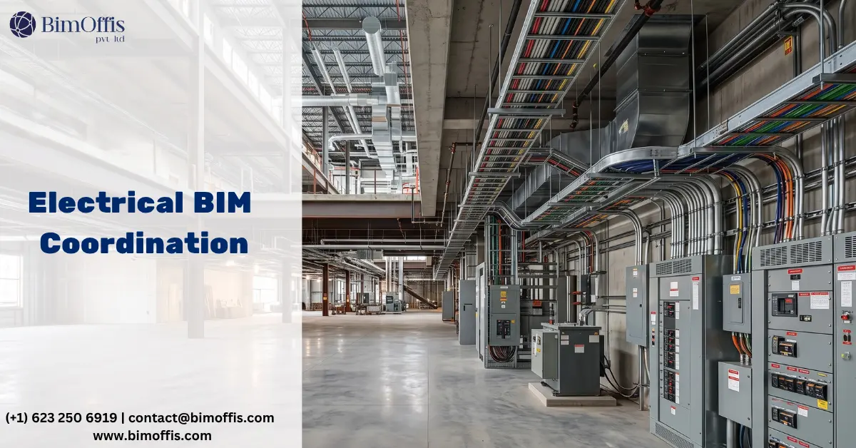
Electrical BIM modeling is the practice that separates MEP projects that run smoothly from the ones that spend their construction phase managing coordination problems that nobody caught during design.
Let me start with something that electrical engineers, mechanical contractors, and site managers all recognise from direct experience.
MEP coordination on a complex building project is genuinely difficult. Every discipline needs space in ceiling voids and risers that every other discipline also needs. The mechanical engineer needs height for ductwork. The plumbing engineer needs space for pipework and drainage falls. The fire protection engineer needs room for sprinkler mains and branches. The electrical engineer needs routes for cable trays, conduits, and switchgear rooms.
When these systems meet on site for the first time during installation, conflicts surface as stopped work, redesigned routes, and variation claims. The electrical contractor removes installed cable trays because the mechanical contractor needs the space first. The plumbing contractor discovers that their drainage fall puts a pipe through a cable tray installed yesterday.
Electrical BIM modeling prevents this. Not by magic. By putting the electrical design into the same three-dimensional environment as every other MEP system and finding conflicts before anyone picks up a tool on site.
What Electrical BIM Modeling Actually Means
Building the Electrical Design in Three Dimensions
Electrical BIM modeling means creating the complete electrical system as an accurate three-dimensional model. Every element represents its real installed geometry. Cable trays sit at their actual width and depth. Conduits follow their actual routes through walls, ceilings, and structural elements. Panels and switchboards sit at their actual dimensional footprints with required clearance zones included. Lighting fixtures sit at their actual ceiling mounting positions.
This is not a visualisation exercise. The purpose is coordination, not presentation. When the electrical model accurately represents the real installed geometry, automated clash detection finds every location where the electrical design conflicts with any other system. Every conflict gets found. Not just the ones visible in plan, but every three-dimensional conflict regardless of where it sits in the building.
Why Accuracy Matters More Than Appearance
A common mistake in electrical BIM modeling is building models that look right rather than models that are right. A cable tray family that represents the tray at a narrower width than the actual installed tray looks correct in a 3D view. However, it misses real conflicts in clash detection. An equipment family that shows the switchboard without its required front clearance zone looks complete. Consequently, it fails to flag the spatial conflict that would prevent safe maintenance access.
Good electrical BIM modeling uses families and geometry that accurately represent real installed dimensions. This includes physical clearances. The model needs to find real conflicts, not only the subset that an idealised representation would produce.
How Electrical BIM Modeling Improves MEP Coordination
Catching Conflicts During Design Rather Than During Installation
The most direct way electrical BIM modeling improves MEP coordination is by moving conflict discovery from the construction phase to the design phase.
When the electrical model sits in the same coordinated environment as the structural model, the architectural model, the mechanical model, the plumbing model, and the fire protection model, automated clash detection checks every electrical element against every other element in the building. The cable tray that would have run through a structural beam gets flagged as a clash during a coordination meeting. The conduit route that would have conflicted with a mechanical duct gets identified in the model. The panel location that would have prevented maintenance access to a mechanical unit appears as a soft clash in the coordination report.
Each of these conflicts costs a model update and a conversation to resolve during design. The same conflicts cost programme delay, rework, and variation claims to resolve during construction. On complex MEP projects where the density of services makes conflicts numerous rather than occasional, the accumulated value of catching those conflicts during design consistently justifies the electrical BIM modeling investment.
Supporting Installation Sequence Planning
Electrical BIM modeling improves MEP coordination beyond simple clash detection. It supports installation sequence planning against real coordinated geometry.
On a large commercial floor plate, multiple MEP trades work in the same ceiling void during the same programme period. The sequence in which trades install their systems matters as much as the positions of those systems. The electrical contractor needs to install certain cable tray sections before the mechanical contractor installs ductwork that would block access to those positions. The plumbing contractor needs to install pipework in a specific sequence relative to the electrical conduit installations in shared riser zones.
When the electrical model accurately represents the installed geometry and the team coordinates it against all other disciplines, the site team plans the installation sequence against real spatial relationships rather than assumed ones. Consequently, the site runs more efficiently and the programme holds more reliably.
Enabling Prefabrication That Actually Works
One of the most significant practical improvements that electrical BIM modeling brings to MEP coordination is enabling genuine electrical prefabrication.
When cable tray routes exist as accurately coordinated three-dimensional geometry in the electrical model, the team can prefabricate sections of cable tray off-site to the exact dimensions the model specifies. The prefabricated sections arrive on site and install in the coordinated positions without field adjustment. This is the efficiency gain that electrical prefabrication promises. However, it only materialises consistently when the model geometry accurately reflects the real installation environment.
Furthermore, electrical BIM modeling supports the coordination of prefabricated electrical assemblies with prefabricated mechanical and plumbing assemblies. When all prefabricated assemblies derive from a coordinated federated model, the interfaces between them work as designed rather than requiring field modification to make assemblies fit together.
The Specific MEP Coordination Benefits of Electrical BIM Modeling
Ceiling Void Coordination
The ceiling void is where most MEP coordination failures originate. Every MEP system needs space in it. None of them gets as much as they would like. Electrical systems, cable trays, conduits, and lighting infrastructure need to fit through what remains after structural, mechanical, and plumbing systems have claimed their share.
Electrical BIM modeling puts the electrical claim on ceiling void space in the same environment as every other claim. The coordination team can see exactly how much space is available in each zone. They can also see which systems are competing for it and how those competing systems can be arranged to fit within the available height. This visibility during design produces ceiling void installations that work on site rather than requiring trades to stop and renegotiate space allocations during installation.
Riser Coordination
Electrical risers carry significant volumes of cable tray, conduit, and busbar trunking through building cores. These cores also carry mechanical, plumbing, and fire protection risers. The interfaces between electrical and other MEP risers need careful coordination. Everything needs to fit within the riser shaft dimensions. Each system also needs the access required for installation and maintenance.
Electrical BIM modeling produces riser models that show every electrical system at its real installed dimensions alongside every other MEP system in the same shaft. The coordination checks that identify conflicts between electrical and other risers happen in the model. They do not happen during installation when the riser shaft is a construction zone with limited access and significant programme pressure.
Plant Room Coordination
Plant rooms carry the highest MEP density of any zone in a building. Switchgear rooms, UPS rooms, and main distribution boards all need significant space. They also require specific clearances that other equipment and services in adjacent plant rooms need to respect.
Electrical BIM modeling in plant rooms ensures that the electrical equipment, its required clearances, and its cable entry and exit routes coordinate against the mechanical plant, the plumbing services, and the structural elements sharing the same space. Plant rooms that have been properly coordinated through electrical BIM modeling install efficiently and commission correctly. Plant rooms where the electrical design was not properly modeled produce the expensive surprises that delay commissioning programmes on complex projects.
What Good Electrical BIM Modeling Looks Like in Practice
Modeling Standards That Serve Coordination
Good electrical BIM modeling starts with modeling standards that require every element to be modeled at its real installed dimensions including required clearances. This standard applies to every element, not just the large ones that are obviously visible in a coordination model.
A 25mm conduit seems too small to worry about in a coordination model of a large commercial building. When thirty 25mm conduits route together through a wall penetration that the architectural team sized without accounting for the electrical requirement, the aggregate becomes a significant coordination problem. Good electrical BIM modeling includes all conduit routes rather than only the major cable tray runs.
Coordination Process That Uses the Model
A well-built electrical BIM model that sits in a shared drive and never gets federated with the other discipline models delivers none of its coordination value. The model needs to be in the coordination environment. It needs checking against other disciplines regularly throughout design development. Furthermore, it needs maintaining as design changes occur.
Good electrical BIM modeling practice runs clash detection regularly throughout design development rather than as a single pre-construction exercise. The electrical coordination lead attends multidiscipline coordination meetings with the current coordinated model rather than with 2D drawings. Moreover, the team implements every clash resolution in the model so that subsequent coordination runs check against the current coordinated design rather than the unresolved original.
The Bottom Line
Electrical BIM modeling improves MEP coordination by putting the electrical design where it belongs throughout the design process. It sits in the same coordinated three-dimensional environment as every other building system, the team checks it systematically for conflicts, and it serves as a reliable reference for installation planning and prefabrication.
The MEP projects that consistently deliver electrical installations that fit in the available space, install on the planned sequence, and commission without coordination surprises are the ones where the team invested in electrical BIM modeling from early design development through to construction handover.
That is what good electrical BIM modeling delivers. And on any MEP project where electrical system density makes coordination failures both likely and expensive, it is worth investing in properly.
Improve MEP coordination with expert Electrical BIM Modeling Services that reduce clashes, rework, and installation errors.
Frequently Asked Questions from Clients
What is Electrical BIM Modeling?
Electrical BIM Modeling creates accurate 3D electrical system models for better design coordination, clash detection, and installation planning.
How does Electrical BIM Modeling improve MEP coordination?
It identifies conflicts between electrical, mechanical, plumbing, fire protection, structural, and architectural systems before construction begins.
Can Electrical BIM Modeling reduce construction rework?
Yes, early clash detection helps prevent installation errors, redesigns, delays, and costly on-site rework.
How does Electrical BIM Modeling help with ceiling void coordination?
It helps teams plan cable trays, conduits, lighting, ducts, and pipes within the available ceiling space.
Does Electrical BIM Modeling support prefabrication?
Yes, accurate 3D electrical models allow cable trays and other assemblies to be prefabricated to coordinated dimensions.
Why is Electrical BIM Modeling important for plant rooms?
It coordinates electrical equipment, clearances, cable routes, and other MEP systems to reduce installation and commissioning problems.