HVAC piping design is one of the most coordination-intensive disciplines in building services engineering. The pipework serving heating and cooling systems routes through ceiling voids, risers, and plant rooms. Every other building system needs the same spaces. Pipework interacts with structural elements, architectural finishes, and competing MEP services. Coordination failures happen regularly on projects where the design process fails to manage those interactions.
BIM has changed how HVAC piping design gets done on serious building projects. The change is not cosmetic. It reaches the core of how pipes get routed. It also reshapes how conflicts with other systems get identified, and how the documentation supporting installation gets produced.
Let’s look at what that change actually looks like in practice.
What HVAC Piping Design Involves
More Than Just Routing Pipes
HVAC piping design covers the complete piping systems that serve a building’s heating, cooling, and ventilation infrastructure. Chilled water systems serve air handling units and fan coil units throughout the building. Hot water systems serve perimeter heating and air handling coils. Condenser water systems serve cooling towers and chillers. Domestic hot and cold water systems can also form part of the design, where these fall within the MEP scope. Pipework connections to chillers, boilers, heat pumps, heat exchangers, and associated plant round out the scope.
Each of these systems carries its own pipe sizing, pressure, insulation, and expansion requirements. Each one also interacts with every other building system in the ceiling voids, risers, and plant rooms it routes through.
Large commercial buildings carry a high volume of HVAC pipework. Combined with dense interaction between building systems, this creates one of the most complex coordination challenges in the building services scope. BIM-based HVAC piping design exists to get this right before installation starts.
How BIM Changes HVAC Piping Design
Three-Dimensional Routing in a Coordinated Environment
BIM’s fundamental contribution to HVAC piping design is a shift. Pipes move from lines on 2D drawings to accurate three-dimensional objects in a coordinated model.
In a 2D piping design workflow, the designer routes pipework on plan and section drawings. Decisions about elevation and spatial positioning rely on the designer’s knowledge and experience with similar systems. Manual overlay of 2D drawings identifies conflicts with other services. Some conflicts get caught this way. Others get missed, because the conflict only exists in three dimensions and the 2D overlay can’t reveal it.
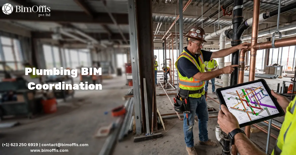
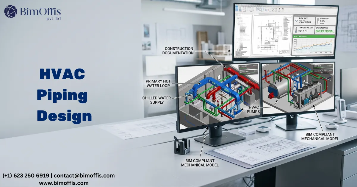
A BIM-based workflow works differently. Every pipe runs as a three-dimensional object at its actual position and actual diameter, including insulation, along its actual route through the building. The pipe model sits in the same coordinated environment as the structural model, the architectural model, the ductwork model, and the electrical model. Automated clash detection then runs across all of these simultaneously. It flags every location where the HVAC pipework conflicts with any other element in the building.
Catching Conflicts During Design
This is where BIM-based HVAC piping design generates its most direct financial and programme value.
Picture a chilled water pipe that routes through a structural beam. During a design coordination meeting, the clash gets flagged. The mechanical engineer adjusts the pipe route in the model. That resolution costs modeling time and a coordination conversation. Discovering the same conflict during installation costs far more. The fix means cutting back a partially installed pipe run, redesigning the route around the structural element, fabricating additional fittings, and reinstalling. That site fix costs many times more than the design coordination that would have prevented it.
Consider the ceiling void on a large commercial floor plate. It carries HVAC pipework alongside ductwork, electrical cable trays, plumbing pipework, sprinkler systems, and lighting infrastructure. 2D drawing overlay cannot reliably manage the interactions between all of these systems. BIM coordination isn’t just a better approach on complex projects. It’s the only approach that manages this coordination complexity reliably.
What BIM-Based HVAC Piping Design Delivers
Accurate Pipework Models That Support Installation
A coordinated BIM model gives the installation team a genuinely useful reference. Teams can see exactly where each pipe runs, at what elevation, and in what direction. They can also check how it connects to adjacent pipes and equipment, and verify clearances around pipes that need maintenance access. Planning the installation sequence against the model beats working from a 2D drawing that demands spatial interpretation.
The BIM model also supports the setting-out process. Pipe support positions, hanger configurations, and bracket locations can all be coordinated in the model and communicated to the installation crew with precision. This precision reduces the improvisation that traditional installation methods demand. It also produces installations that more consistently match the design intent.
Fabrication-Ready Pipework Information
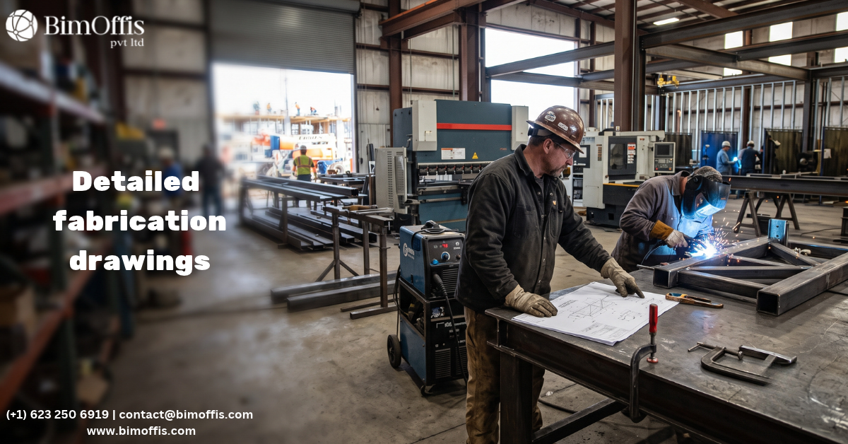
BIM-based HVAC piping design supports off-site pipework fabrication in ways 2D workflows cannot match. Pipework runs exist as accurately coordinated three-dimensional geometry. From that geometry, the model can generate pipe spool drawings with the exact dimensions, bend angles, flange positions, and branch configurations the workshop needs.
Fabricated pipe spools arrive on site and connect to adjacent elements correctly. That happens because the geometry was accurate and coordinated before fabrication started. Off-site fabrication offers real efficiency gains: reduced site labour, improved quality control, and faster installation. Those gains only materialise when the fabrication information is accurate, and BIM-based design is what makes that accuracy achievable.
Documentation That Reflects Coordinated Design
A coordinated BIM model changes where documentation comes from. Procurement and construction documentation comes straight from the model, rather than from a separate manual process running alongside it.
The model automatically generates pipe schedules listing every pipe run, its diameter, material, insulation specification, and pressure rating. It also generates equipment connection schedules for every connection to every piece of HVAC equipment. Valve and fitting schedules follow the same path. When the coordination process changes a pipe route, the documentation updates automatically to reflect the current design.
This accuracy carries direct financial value for mechanical contractors managing procurement against a construction programme. Procurement quantities drawn from the coordinated model prove more reliable than quantities from manual takeoff of 2D drawings. The procurement process then runs with less uncertainty, and the risk of material shortfalls or excess orders drops.
Where BIM-Based HVAC Piping Design Makes the Most Difference
Large Commercial Buildings
Large commercial office buildings, mixed-use developments, and high-rise residential projects carry HVAC piping systems complex enough to justify BIM-based design. The density of HVAC pipework plays a part. So does the density of competing services in ceiling voids and risers. Together, they make coordination failures both more likely and more expensive on large commercial projects than on simpler building types.
Healthcare Facilities
Healthcare buildings carry HVAC piping systems at a density and complexity that exceeds most other building types. Operating theatres, intensive care units, and specialist clinical spaces all compete for the same spatial zones. Heating, cooling, medical gas, and domestic water systems all need room there. Regulatory requirements governing HVAC in healthcare environments add further specification complexity, which makes accurate BIM-based documentation particularly important.
Data Centers
Data center HVAC piping design involves precision cooling systems where spatial coordination proves critical to commissioning performance. Chilled water pipework, condenser water systems, and specialist cooling systems all interact in tight environments. Coordination failures discovered during commissioning can threaten the project’s go-live date. For exactly this reason, BIM-based HVAC piping design is standard practice on serious data center projects.
The Bottom Line
BIM-based HVAC piping design delivers value across the full lifecycle of an HVAC piping project. Better coordination during design catches conflicts before they become expensive site problems. More accurate routing produces models that support reliable installation. Fabrication-ready documentation enables off-site fabrication that improves installation efficiency. Documentation drawn from the model, rather than produced separately, stays accurate through design changes and serves procurement and construction reliably.
BIM-based design isn’t an enhancement to consider for any building project with meaningful HVAC piping complexity. It’s the approach that makes reliable HVAC piping design and installation achievable.
Optimize your HVAC systems by working with our BIM MEP specialists for accurate piping design and coordination.
Frequently Asked Questions from Clients
What is BIM-Based HVAC Piping Design?
It uses BIM technology to create accurate HVAC piping models for construction.
Why is BIM important for HVAC piping design?
It improves coordination, reduces clashes, and enhances installation accuracy.
Which software is used for HVAC BIM modeling?
Autodesk Revit, Navisworks, and AutoCAD MEP are commonly used.
How does BIM reduce HVAC installation errors?
It detects design conflicts before construction begins.
Which projects benefit from BIM-based HVAC piping design?
Commercial, residential, industrial, healthcare, and infrastructure projects.
What are the benefits of BIM-Based HVAC Piping Design?
Better coordination, faster project delivery, reduced rework, and improved construction quality.